Eureka AIR delivers breakthrough ideas for toughest innovation challenges, trusted by R&D personnel around the world.

Video-endoscopic intubation stylet

Pending Publication Date: 2021-07-22
ETH ZZURICH +1
View PDF0 Cites 1 Cited by
  • Summary
  • Abstract
  • Description
  • Claims
  • Application Information

AI Technical Summary

Benefits of technology

The invention is a video-endoscopic intubation stylet that is automatically or manually guided towards the trachea for tracheal intubation with an endotracheal tube. It has a bendable end section with a camera at the tip that can detect the direction of light signals and adjust the bending motion of the end section accordingly. This allows for easier and more accurate guided intubation. The intubation stylet can be used in both automatic and manual modes and is equipped with a control unit for controlling the bending motion of the end section. The control unit can also interact with a screen or wirelessly with the rest of the intubation stylet. The control unit can also have a microprocessor and database to manage stored data and adapt the orientation of the tip automatically for maximizing light intensity detection. The technical effects of the invention include improved guided intubation, reduced malfunctions due to distracting signals, and improved visualization during tracheal intubation.

Problems solved by technology

Sometimes the decision in which direction the tip should be orientated is not very easy.

Method used


Image

  • Video-endoscopic intubation stylet
  • Video-endoscopic intubation stylet
  • Video-endoscopic intubation stylet

Examples


first embodiment

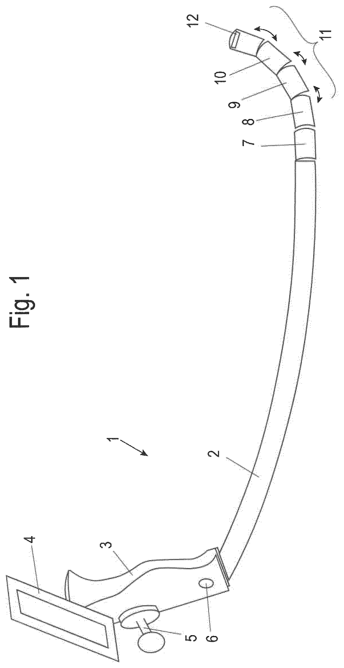
[0089]FIG. 1 illustrates an inventive intubation stylet 1 according to the invention. The intubation stylet 1 comprises a shaft 2, a control unit 3 with a screen 4 for visualization of the position of a tip 12 of the shaft 2 of the intubation stylet 1.

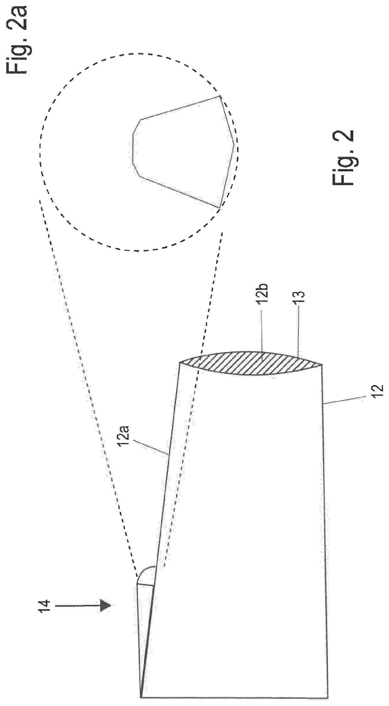
[0090]The tip 12 is part of a bendable end section 11 comprising a plurality of linked segments 7-10 and 12. Each segment can be bend to a certain angle to a neighboring segment.

[0091]Each segment defines a longitudinal axis. A bending angle is defined between two neighboring segments or between the rigid part of the shaft 2 and the first neighboring segment 7 after the rigid part of the shaft. The bending angles between two neighboring segments 7-8, 8-9, 9-10, 10-12, increases from rigid part of the shaft 2 to the tip 12.

[0092]The control unit 3 includes a control button for switching between to operation modes of the intubation stylet 1. The control unit 3 further includes an actuating element 5, such as a joystick, for the bending m...

second embodiment

[0197]FIG. 10 discloses an inventive intubation stylet 41 according to the invention. The stylet comprises identically to the stylet of FIG. 1 a shaft 42 and a control unit 43 with a screen 44 for visualization of the position of a tip 52 of the shaft 42 of the intubation stylet 41.

[0198]The tip 52 is part of a bendable end section 51 comprising a plurality of linked segments 47-50 and 52. Each segment can be bend to a certain angle to a neighboring segment. The control unit 43 is further provided with an actuating element 45, such as a joystick, for the bending movement of the tip 52 or any other orientation of the tip 52 relative to the shaft 42. The control unit 43 may further comprise an on- / off-Bottom 46 to switch the stylet off or on.

[0199]The control may be provided by the actuating element 45 in the same way as described in FIG. 1-9.

[0200]The control unit 43 may further comprise a switch 53, such as a monostable switch, which function will be explained.

[0201]In FIGS. 11 and ...


PUM


Abstract

An intubation stylet includes a shaft with a bendable end section having a tip and a camera at the tip for providing an image of a part of the environment of the tip. The stylet includes a control unit for control of the bending motion of the end section. The control unit is adapted to work under at least two operation modes. In a first of the two operation modes the bending motion of the end section is guided automatically by an orientation of the tip. In a second operation mode, the bending motion of the end section is controlled by manual control of a user without an automatically guidance. The control unit is further adapted to operate in the second operation mode when the first operation mode is inactive.

Description

BACKGROUND AND SUMMARY OF THE INVENTION[0001]Exemplary embodiments of the invention relate to a video-endoscopic intubation stylet for the guided tracheal intubation with an endotracheal tube, which is automatically guided by light emanating from the trachea or which is manually guided by an image transmitted from a camera at the tip to a video monitor.[0002]Intubation stylets are known in the art. In the current state of the art, numerous guiding methods for conventional and digital intubation stylets have been developed.[0003]Conventional intubation stylets are inserted through the mouth and are guided by the user. A camera is positioned at the tip surface of the end section. The tip can be orientated mechanically by steering the intubation stylet with the help of a handle that is a part of the handpiece. Sometimes the decision in which direction the tip should be orientated is not very easy. Therefore an automatically guided intubation stylet has been developed.[0004]One example ...

Claims


Application Information

Patent Timeline
IPC IPC(8): A61M16/04A61B1/005A61B1/267
CPCA61M16/0488A61B1/0052A61B1/267A61M2205/502A61M2205/332A61M2205/505A61M2205/3313A61M16/0418A61B1/00006A61B1/00052A61B1/05A61B5/065A61B1/0016A61B2034/301A61B34/32A61B2090/3945A61M2205/583A61M2205/3592A61M2205/3569A61M2205/50A61M2205/10A61M2205/3375A61M2205/8206A61M2205/587A61M2209/088A61B1/00097
Inventor BIRO, PETERBOEHLER, QUENTINCHAUTEMS, CHRISTOPHENELSON, BRADLEY JAMES
Owner ETH ZZURICH
Why Eureka
Eureka Blog
Learn More