System and method for improved RF pulse width modulation

a pulse width modulation and pulse width technology, applied in pulse automatic control, pulse technique, logic circuits characterised by logic functions, etc., can solve the problem that the achievable amplitude of rfpwm is inherent lower bound, dynamic range limitations, and still have not gained widespread commercial deploymen

Active Publication Date: 2021-07-22
ARIZONA STATE UNIVERSITY
View PDF0 Cites 7 Cited by
  • Summary
  • Abstract
  • Description
  • Claims
  • Application Information

AI Technical Summary

Benefits of technology

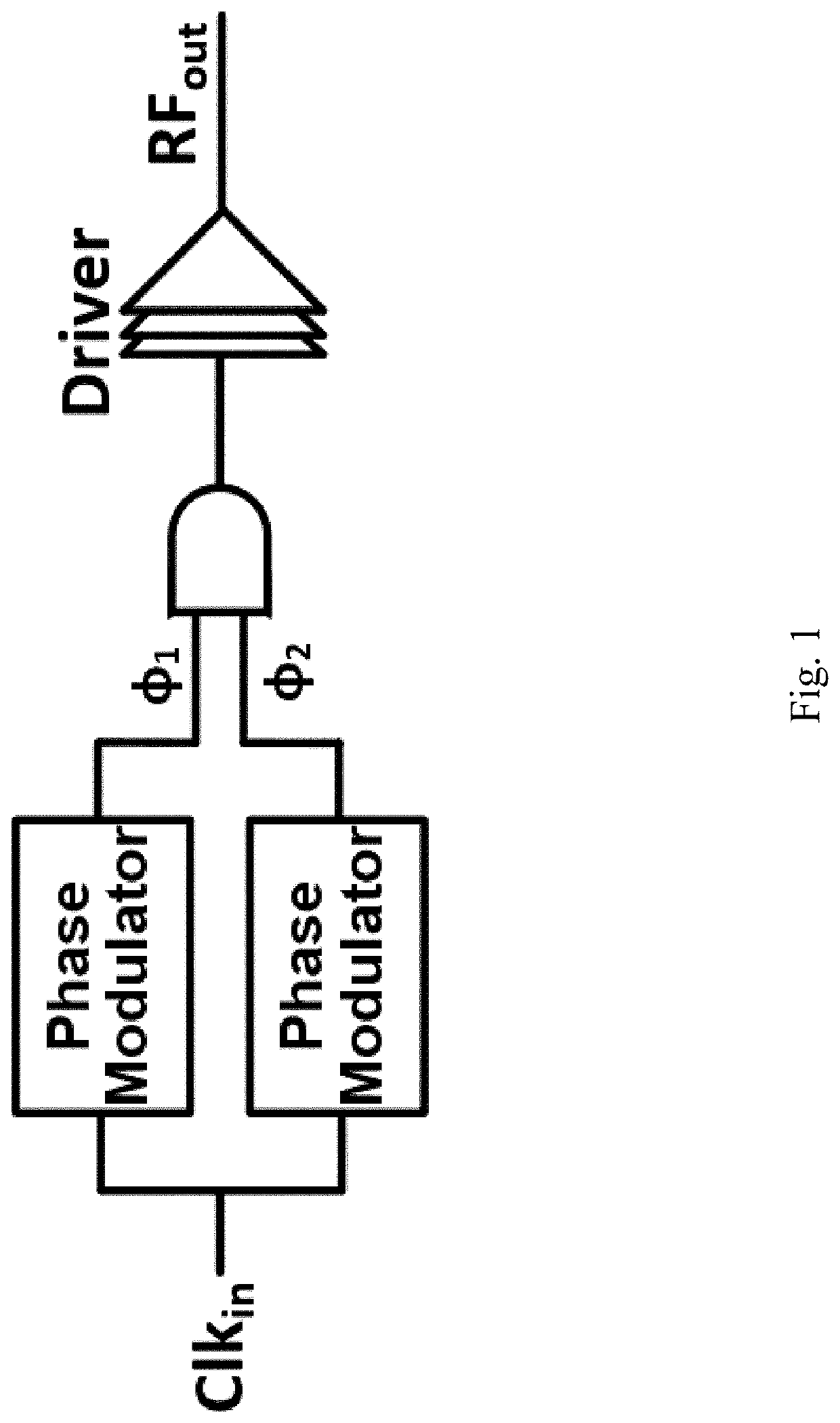
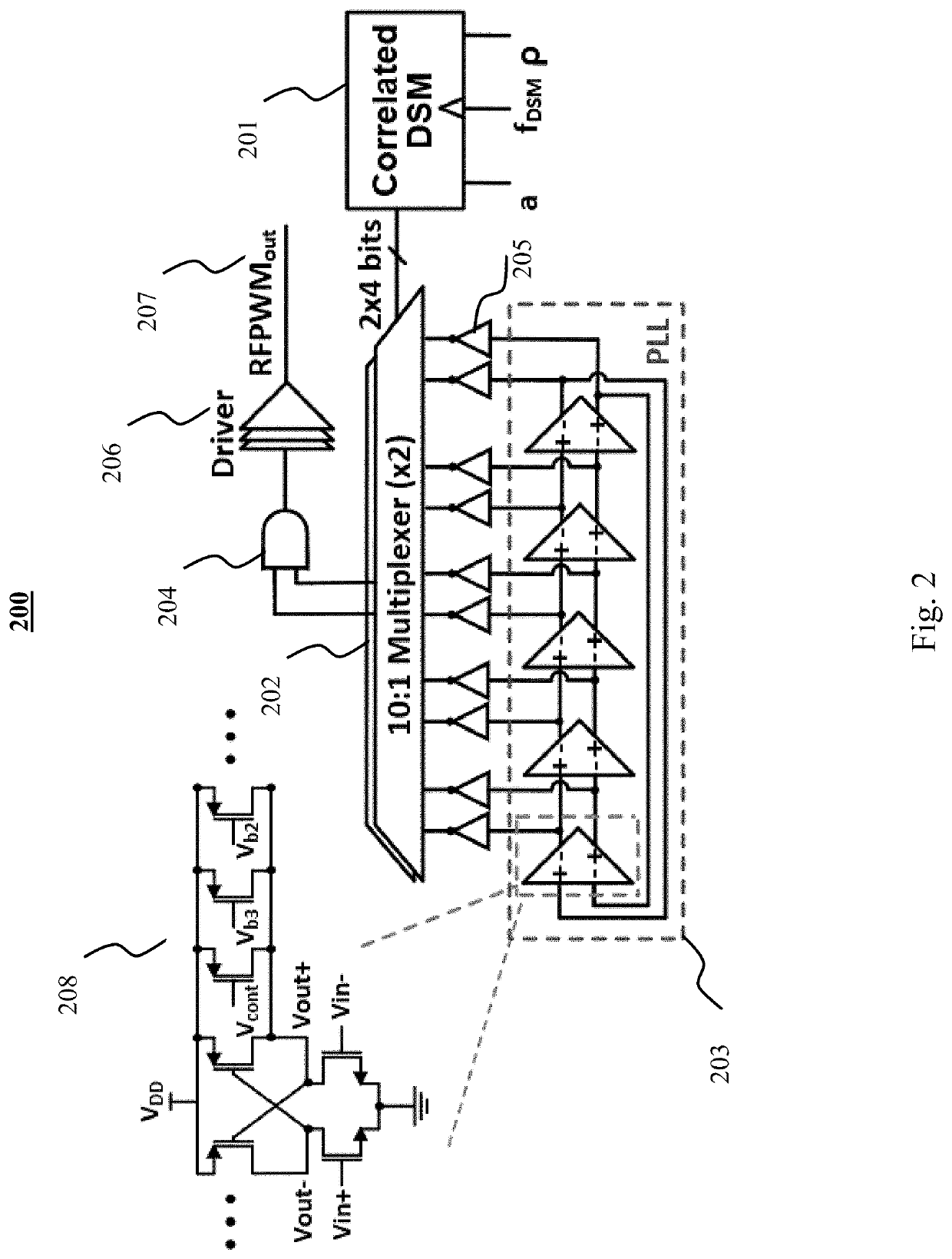
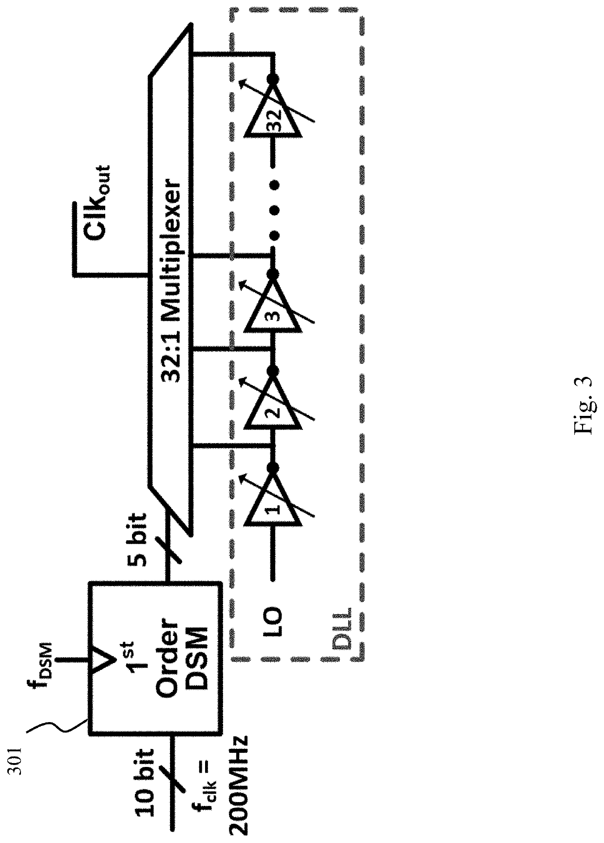
This patent describes a system and method for generating an RFPWM signal. The system includes a delta sigma modulator, a phase-locked loop, phase quantization, a multiplexer, a driver, and a buffer. The method includes generating multiple phase quantizations, selecting one as the output of the multiplexer, and generating an RFPWM output signal. The technical effects of this system and method include improved dynamic range, faster response time, and more reliable performance.

Problems solved by technology

Despite all these advantages, they still have not gained widespread commercial deployment.
One of the reasons for this is because of the inherent dynamic range limitations of the most popular method by which polar modulators generate their amplitude modulation.
Unfortunately, RFPWM's achievable amplitude has an inherent lower bound due to pulse width distortion and pulse swallowing.
This means that traditional RFPWM systems are often not suitable for transmitting high peak-to-average power ratio (PAPR) communication standards such as WLAN.
Even if the desired pulse width is greater than the rise time, small pulse widths suffer from high levels of distortion and sensitivity to clock jitter.
In addition to limited dynamic range, RFPWM systems also suffer from limited resolution.
At RF frequencies, it can be difficult to generate more than a few quantizations, especially if the phase shifter requires wideband reconfigurability.
Unfortunately, for adequate resolution, typically hundreds or thousands of these interpolator units are required, which makes the circuit highly sensitive to PVT and consumes significant area and power.
Because the process variations in each of these device types is largely uncorrelated, the variation in interpolators using a combination of device types is expected to result in lower yields.
However, doing so can yield nonlinearities and non-uniformly spaced phase quantizations if not well-calibrated.
Furthermore, this method does nothing to mitigate the dynamic range limitations associated with pulse swallowing.
Unfortunately, these techniques do not generally scale well.
In particular, there is a practical limit to the number of power amplifiers (PAs) that can be combined, as well as the fact that combiners occupy large areas and introduce significant loss, thus degrading the PA efficiency.
Multilevel outputs also do not scale well for the same reasons, as well as the fact that they are not compatible with standard binary circuits.
Similarly, outphasing circuitry occupies significant area and introduces loss due to the power combiners required.
However, the phase resolution of BBPWM systems is still limited by phase modulator quantization, and therefore still requires phase interpolator units.

Method used


Image

  • System and method for improved RF pulse width modulation
  • System and method for improved RF pulse width modulation
  • System and method for improved RF pulse width modulation

Examples


experimental examples

[0086]The invention is further described in detail by reference to the following experimental examples. These examples are provided for purposes of illustration only, and are not intended to be limiting unless otherwise specified. Thus, the invention should in no way be construed as being limited to the following examples, but rather, should be construed to encompass any and all variations which become evident as a result of the teaching provided herein.

[0087]Without further description, it is believed that one of ordinary skill in the art can, using the preceding description and the following illustrative examples, make and utilize the system and method of the present invention. The following working examples therefore, specifically point out the exemplary embodiments of the present invention, and are not to be construed as limiting in any way the remainder of the disclosure.

System Design

[0088]A correlated ΔΣM was implemented as shown in FIG. 10 comprising two standard 8 bit digita...


PUM


Abstract

A system for generating an RFPWM signal comprises a delta sigma modulator having a plurality of outputs, a phase-locked loop comprising a plurality of phase quantization outputs, at least one multiplexer having a plurality of signal inputs, a plurality of selector inputs, and at least one output, the signal inputs communicatively connected to the phase quantization outputs of the phase-locked loop and the selector inputs electrically connected to the outputs of the delta sigma modulator, and a driver having an input communicatively connected to the output of the multiplexer and an output generating an RFPWM signal. A method of generating an RFPWM signal is also described.

Description

CROSS-REFERENCE TO RELATED APPLICATIONS[0001]This application claims priority to U.S. Provisional Patent Application No. 62 / 964,288, filed on Jan. 22, 2020, incorporated herein by reference in its entirety.\STATEMENT REGARDING FEDERALLY SPONSORED RESEARCH OR DEVELOPMENT[0002]This invention was made with government support under D16AP00094 awarded by the Defense Advanced Research Projects Agency. The government has certain rights in the invention.BACKGROUND OF THE INVENTION[0003]Digital transmitters offer frequency flexibility, process, voltage, and temperature (PVT) tolerance, and benefit from technology scaling. Despite all these advantages, they still have not gained widespread commercial deployment. One of the reasons for this is because of the inherent dynamic range limitations of the most popular method by which polar modulators generate their amplitude modulation. This method is known as RF Pulse Width Modulation (RFPWM) and is accomplished by ANDing two phase shifted copies o...

Claims


Application Information

Patent Timeline
IPC IPC(8): H03K3/012H03K3/017H03M3/00H03L7/08H03K19/20
CPCH03K3/012H03K3/017H03K19/20H03L7/08H03M3/30H03K7/08H03K3/0322H03K3/0315H03L7/0996H03L7/089H03L7/0895H03L7/093H03L7/0812
Inventor GROUT, KEVIN
Owner ARIZONA STATE UNIVERSITY
Why Eureka
Try Eureka