Cleaning robot, control method for same, and cleaning robot system

a technology of cleaning robots and robots, which is applied in the direction of cleaning action control, carpet cleaners, instruments, etc., can solve the problems of manual work of users, poor cleaning effect of mop, and increasing number of stains attached to the mop, so as to achieve convenient user operation and flexible control

Pending Publication Date: 2021-07-29
POSITEC POWER TOOLS (SUZHOU) CO LTD
View PDF0 Cites 5 Cited by
  • Summary
  • Abstract
  • Description
  • Claims
  • Application Information

AI Technical Summary

Benefits of technology

[0043]The foregoing embodiments have the following beneficial effects: the user can trigger the cleaning robot to return to the base station for maintenance, an operation of the user is more convenient, and the robot is more flexibly controlled.

Problems solved by technology

Inevitably, a longer mopping time of the rag indicates a poorer cleaning effect of the mop, and a growing number of stains will be attached to the mop.
For this reason, a user has to regularly remove, clean, and replace the rag with a clean mop, so that a manual work for the user will reduce the automated operating experience of the robot.
The user frequently intervenes to charge the robot, so that use experience of the user is affected, and the intelligence of the cleaning robot is reduced.
A growing number of ornaments such as a carpet are used in the existing indoor environment, when the mopping robot moves to the carpet, a mopping component is in contact with the carpet, frictional resistance exists, and the carpet is easily damaged by scraping or pollution.

Method used


Image

  • Cleaning robot, control method for same, and cleaning robot system
  • Cleaning robot, control method for same, and cleaning robot system
  • Cleaning robot, control method for same, and cleaning robot system

Examples


embodiment a

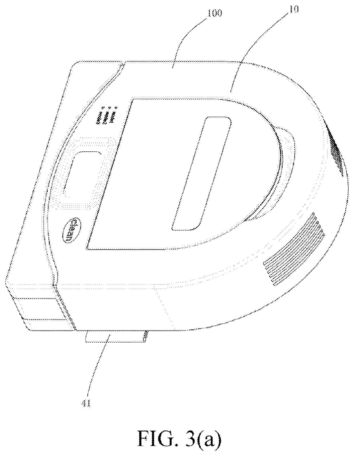
[0110]When detecting that a ground has changed from a hard ground state to a carpet state, the ground sensor sends a signal to the control mechanism, the control mechanism controls the elevating motor to start forward rotation, and the elevating transmission mechanism formed through cooperation of the gear and the rack drives the mounting board 41 to rise. In this way, the wiping unit connected to the mounting board 41 may also be lifted, thereby avoiding an obstacle formed by the carpet. On the contrary, when detecting that the ground has changed from the carpet state to the hard ground state, the ground sensor sends a signal to the control mechanism, the control mechanism controls the elevating motor to perform reverse rotation, and the elevating transmission mechanism formed through cooperation of the gear and the rack drives the mounting board 41 to fall. In this way, the wiping unit connected to the mounting board 41 also falls, thereby restoring a state of contacting the hard ...

embodiment b

[0112]FIG. 9 is a process in which a cleaning robot 100 controls a mounting board 41 to lift up or down when encountering a doorsill according to an embodiment. The cleaning robot 100 works on a hard ground floor. In this case, an elevating mechanism is not started, and the mounting board 41 closely contacts the hard ground floor. In a walking process of the cleaning robot 100, the ground sensor detects a ground state. When the ground sensor detects that a front ground is a protruded obstacle, for example, a doorsill, the cleaning robot 100 needs to pass over the doorsill, and the cleaning robot 100 is ready to lift the wiping unit. In this case, a signal is sent to the control mechanism, and the control mechanism controls the elevating motor to perform forward rotation and drives the elevating transmission mechanism to start, so as to control the mounting board 41 to drive the wiping unit to rise. When the cleaning robot 100 drives away from the doorsill, a signal is sent to the co...

embodiment c

[0113]FIG. 10 is a process in which a cleaning robot 100 controls a mounting board 41 to lift up or down when encountering a doorsill according to an embodiment. The cleaning robot 100 works on a hard ground floor. In this case, an elevating mechanism is not started, and the mounting board 41 closely contacts the hard ground floor. In a walking process of the cleaning robot 100, the ground sensor detects a ground state. When the ground sensor detects that a front ground is a protruded obstacle, for example, a doorsill, the driving gear 21 of the cleaning robot 100 needs to pass over the doorsill, and a front portion of the cleaning robot 100 is first lifted, and the tilt sensor senses the lifting of the front portion of the robot 100. In this case, a signal is sent to the control mechanism, and the control mechanism controls the elevating motor to perform forward rotation and drives the elevating transmission mechanism to start, so as to control the mounting board 41 to drive a rag ...


PUM


Abstract

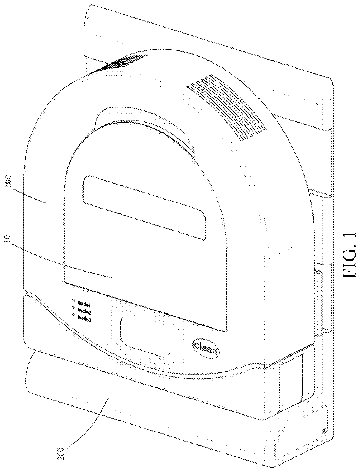
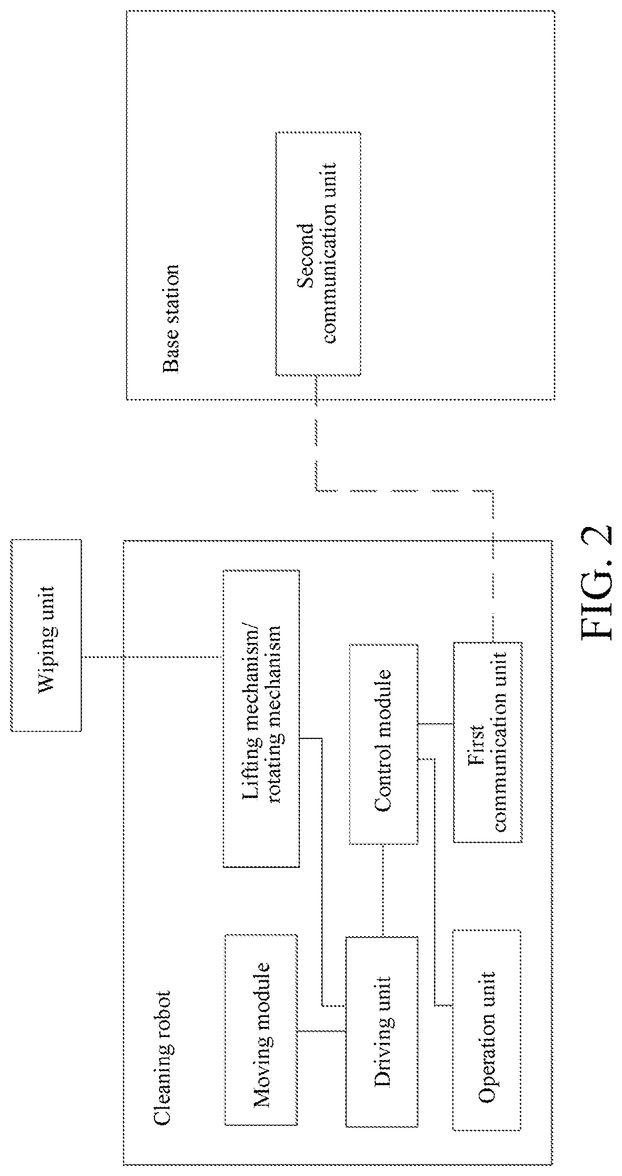
A cleaning robot, including: a housing; a moving module, and a control module, for controlling the moving module to drive the cleaning robot to move. When the cleaning robot moves on a working surface, a wiping unit is capable of directly or indirectly contacting the working surface to wipe the same. The cleaning robot includes a work execution state and a maintenance state. While the cleaning robot is switching from the work execution state to the maintenance state, the control module controls the cleaning robot to move from a work execution position corresponding to the work execution state to a maintenance position corresponding to the maintenance state. During at least a part of the process of the cleaning robot moving from the work execution position to the maintenance position, where the at least a part of the wiping unit is in a state of not contacting the working surface.

Description

[0001]This application is a National Stage Application of International Application No. PCT / CN2019 / 090603, filed on Jun. 10, 2019, which claims benefit of and priority to Chinese Patent Application No. 201810590281.9, filed on Jun. 8, 2018 and Chinese Patent Application No. 201810588911.9, filed on Jun. 8, 2018, all of which are hereby incorporated by reference in their entirety for all purposes as if fully set forth herein.BACKGROUNDTechnical Field[0002]The present invention relates to a cleaning robot, control method for same, and cleaning robot system.Related Art[0003]As requirements of a user are diversified, types of existing cleaning robots are increased, and a wiping robot (hereinafter also referred to as a mopping robot) is one of the cleaning robots. A mopping robot has a sweeping function and a mopping function at the same time, for example, a mopping robot is provided with a mopping assembly for wiping a cleaned ground in addition to a rolling brush for sweeping and dust ...

Claims


Application Information

Patent Timeline
Patent Type & Authority Applications(United States)
IPC IPC(8): A47L11/40A47L11/28A47L11/282G05D1/02H02J7/00
CPCA47L11/4069G05D2201/0203A47L11/4005A47L11/4011A47L11/4055A47L11/4066A47L11/4091A47L11/4036A47L11/282G05D1/0225H02J7/0047H02J7/0042A47L2201/022A47L2201/04A47L2201/06A47L11/28A47L11/40A47L11/4002A47L11/4052A47L2201/026A47L2201/02A47L11/4072A47L11/4061H02J7/0048H02J7/0049H02J7/00034G05D1/0217
Inventor ZHANG, SHISONGZHONG, HONGFENGXIE, MINGJIANXU, JIANQIANGLI, JI
Owner POSITEC POWER TOOLS (SUZHOU) CO LTD
Why Eureka
Try Eureka