Electron Beam Apparatus

a technology of electron beam and beam tube, which is applied in the direction of electrical apparatus, electric discharge tubes, basic electric elements, etc., can solve the problems of expanding the irradiation area and the inability to obtain clear ecp images, and achieve accurate spherical aberration correction

Pending Publication Date: 2021-07-29
HITACHI HIGH-TECH CORP
View PDF0 Cites 0 Cited by
  • Summary
  • Abstract
  • Description
  • Claims
  • Application Information

AI Technical Summary

Benefits of technology

[0010]By setting a phase change amount suitable for a scanning mode, accurate spherical aberration correction can be performed even at different scanning speeds.

Problems solved by technology

When the electron beam deviates significantly out of the axis and passes through the objective lens, the electron beam is not fixed at one point due to spherical aberration of the objective lens, an irradiation area expands, and a clear ECP image cannot be obtained.

Method used


Image

  • Electron Beam Apparatus
  • Electron Beam Apparatus
  • Electron Beam Apparatus

Examples


Embodiment Construction

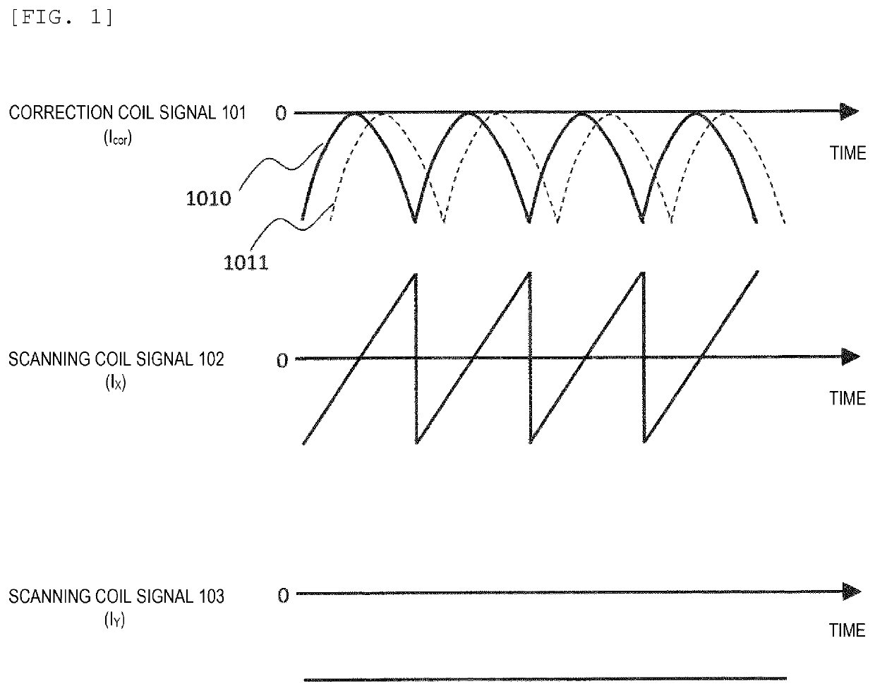
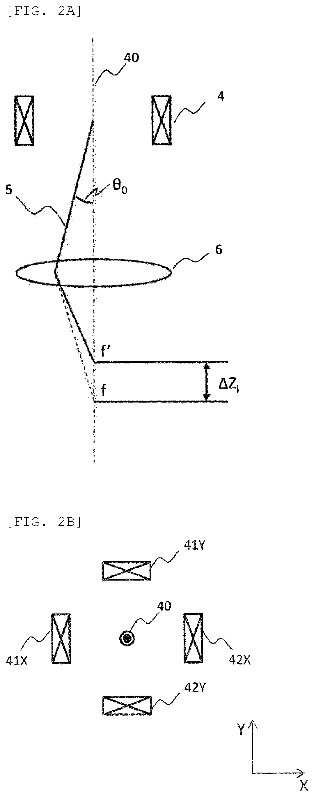
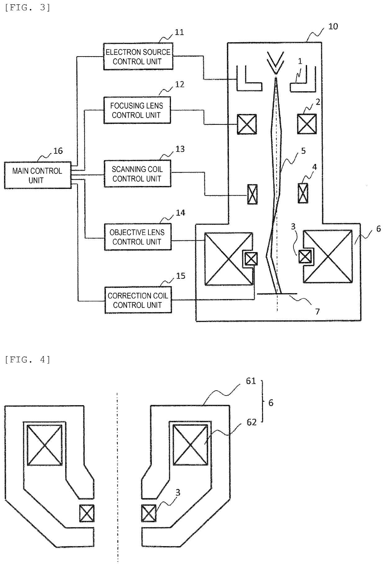
[0019]FIG. 3 illustrates a schematic configuration diagram of an electron optical system in an electron beam apparatus that obtains an ECP image. An electron beam 5 emitted from an electron source 1 is focused by a focusing lens 2 and deflected by a scanning coil 4. An objective lens 6 swings back the electron beam 5 deflected to the outside of an optical axis by the scanning coil 4 to form a magnetic field for performing angular scanning on a surface of a sample 7. As described above, when a deflection angle deviates significantly out of the axis from several degrees to tens of degrees, an irradiation position of the electron beam 5 is not fixed at one point due to spherical aberration of the objective lens 6, an irradiation area expands, and a clear ECP image cannot be obtained. Therefore, a correction coil 3 which corrects the spherical aberration of the objective lens 6 is provided, and the spherical aberration of the objective lens 6 is corrected by exciting the correction coil...


PUM


Abstract

In an electron beam apparatus performing angular scanning that changes an incident angle of an electron beam incident at a predetermined incident position on a sample, when a correction coil is provided in a gap portion of a yoke (magnetic path) of an objective lens, spherical aberration can be corrected by following a deflection signal even if a deflection frequency increases. Therefore, a main control unit that controls an electron optical system sets predetermined phase change amounts a, b with respect to control of a scanning coil in control of the correction coil, and the predetermined phase change amounts a, b are made different depending on a plurality of scanning modes having different scanning speeds.

Description

TECHNICAL FIELD[0001]The present invention relates to an electron beam apparatus such as a scanning electron microscope and a transmission electron microscope, and particularly to an electron beam apparatus suitable for observation of an electron channeling pattern.BACKGROUND ART[0002]As an application of a scanning electron microscope (SEM) or a transmission electron microscope (TEM), there is a selected area electron channeling pattern (SACP) method that can obtain a microscopic crystal structure of an observation portion. In the SACP method, an electron channeling pattern (ECP) image can be obtained by fixing an electron beam at one point on a sample and performing angular scanning that changes an incident angle of the electron beam. A crystal structure and crystal strain of the sample can be analyzed from crystal orientation distribution in the sample appearing in the ECP image.[0003]When the angular scanning is performed to obtain the ECP image, the electron beam is deflected b...

Claims


Application Information

Patent Timeline
Patent Type & Authority Applications(United States)
IPC IPC(8): H01J37/147H01J37/28H01J37/141H01J37/153
CPCH01J37/1475H01J37/153H01J37/141H01J37/28H01J37/1478H01J2237/1506H01J2237/1534H01J2237/2803
Inventor YAMAZAWA, YU
Owner HITACHI HIGH-TECH CORP
Why Eureka
Try Eureka