

Carbon Nanotube Sensors, Articles, and Methods
a carbon nanotube and sensor technology, applied in the field of carbon nanotube sensors, articles, and methods, can solve the problems of m/m, semiconductor strain gauges have outperformed the cheaper metallic-printed sensors, and are difficult to detect subtle micro-strains (m/m), and semiconductor strain gauges are difficult to detect, and the strain range of semiconductor strain gauges is limited. , temperature-dependent, fragile, and expensiv
- Summary
- Abstract
- Description
- Claims
- Application Information
AI Technical Summary
Benefits of technology
Problems solved by technology
Method used
Image

Examples
example 1
l Carbon Nanotube Buckypaper Fabrication
[0078]The fabrication process of this example for creating a carbon nanotube buckypaper (CNT-BP) included creating a uniform dispersion of CNTs via sonication.
[0079]Multi-wall CNTs (MWCNTs) were used in this example. The MWCNT-BPs produced in this example were 6 μm thick, exhibited an electrical conductivity of 200 S / cm, and had an elastic modulus of nearly 3 GPa.
[0080]The buckypaper fabrication procedure of this example was similar to procedures disclosed in the literature, however, TRITON®-X surfactant (HONEYWELL FLUKA™, USA) was added to the suspensions to improve the CNT dispersions by reducing the surface energies between CNT bundles.
[0081]The TRITON®-X surfactant (HONEYWELL FLUKA™, USA) was added to reduce or minimize the number of large CNT bundles in the dispersions. Highly dispersed CNTs were believed to facilitate higher quality buckypapers in terms of mechanical and / or electrical properties.
[0082]After dispersing the CNTs, the suspe...
example 2
rinted Sensor
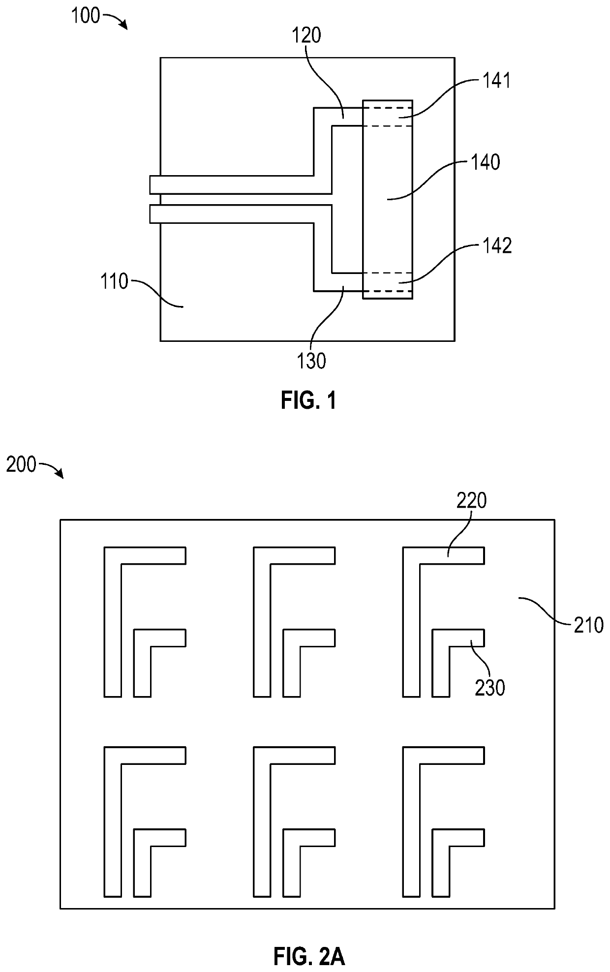
[0088]The sensor structure of this example included a strip of buckypaper (20 mm×3 mm×0.006 mm), a polyethylene terephthalate (PET) substrate with printed circuitry on its surface, and a laminated film to protect the sensor components and hold the BP strip in position.
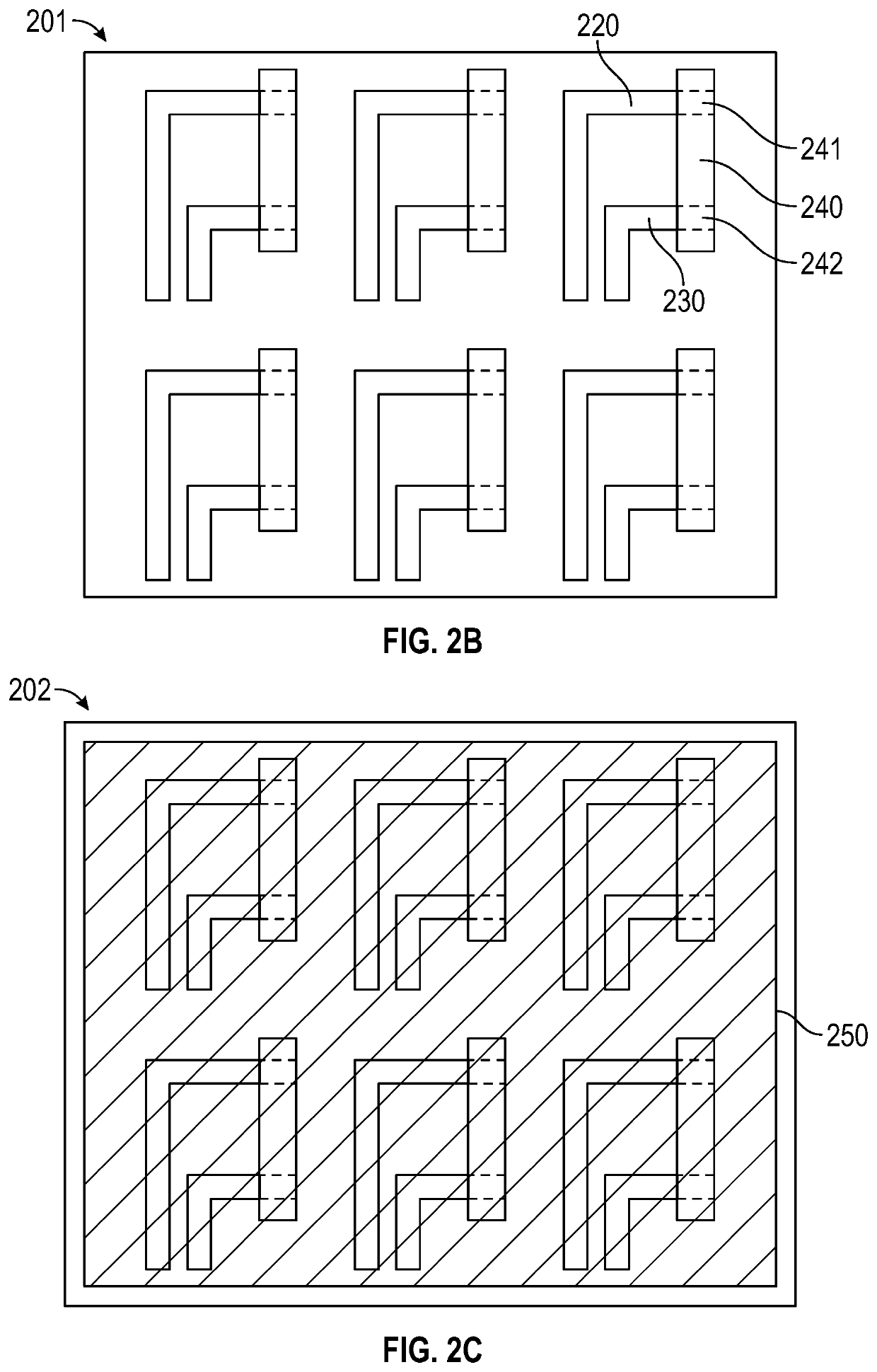
[0089]The manufacturing process of this example included [1] printing silver electrodes on a polymer substrate with a commercially-available ink-jet printer, [2] positioning the strips of buckypaper on the electrodes, and [3] laminating the polymer substrate onto which the buckypaper strips had been positioned.
[0090]The manufacturing process of this example was low-cost and scalable due at least in part to the simplicity and commercial availability of the printing technology.
[0091]The silver ink electrodes were printed on a thin PET substrate using a low-cost, commercial one-pass printer (i.e., EPSON® STYLUS® inkjet printer).
[0092]A commercially available, water-based silver ink was used (METALON® conducti...
example 3
ization
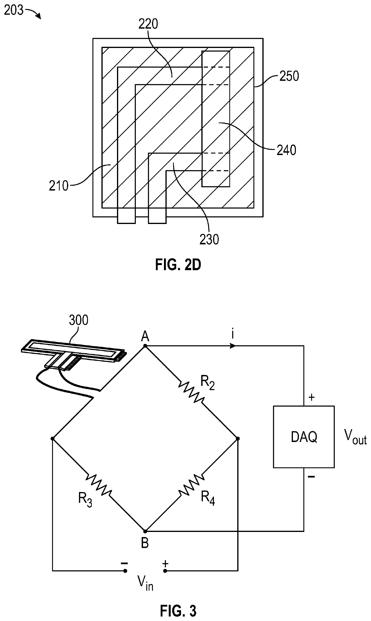
[0102]Strain gauge measurements were carried out using a DEWESOFT® SIRIUS® STG-Multi card. The printed sample was fastened to a flexible polyvinyl chloride (PVC) substrate (150 mm×25 mm×3 mm) using an epoxy-based adhesive. The PVC substrate was fixed to a linear actuator (NITEK® GDI 350ES500S), and the actuator applied periodic (1 Hz) strains of 0.4% with highly accurate positional control.
[0103]To better access the sensor's performance, a metallic, commercial strain gauge with a gauge factor of 2.5 was also fastened to the PVC substrate. Both strain gauges were connected to a Wheatstone bridge, and the measurements were recorded on a DEWESOFT® data acquisition card.
[0104]The buckypapers' electrical resistance included three components: (1) the intrinsic resistance (RIndividual) of the individual CNTs, (2) the contact resistance (RContact) between the CNTs, and (3) the tunneling resistance (RTunneling) between the CNTs.
[0105]However, RIndividual played a negligible role in th...
PUM
 Abstract
Description
Claims
Application Information