Capacitor

a technology of capacitors and capacitors, applied in the direction of capacitors, fixed capacitor combinations, fixed capacitor housings/encapsulations, etc., can solve the problems of inability to achieve sufficient cooling, inability to perform sufficient heat recovery at a portion separated from the cooling pipe, and low cooling performan

Active Publication Date: 2021-08-12
MEIDENSHA ELECTRIC MFG CO LTD
View PDF0 Cites 5 Cited by
  • Summary
  • Abstract
  • Description
  • Claims
  • Application Information

AI Technical Summary

Benefits of technology

[0011]When temperature (ambient temperature) of a surrounding atmosphere is high, since the outer case that is subject to heat from the surrounding atmosphere and the inner case are thermally insulated from each other by a refrigerant flowing in the refrigerant flow passages, heat transfer to the capacitor element is suppressed. In particular, the refrigerant flow passages are formed so as to enclose almost the whole of the capacitor element except for the opening surface where the terminals are arranged. This prevents a part of the capacitor element from being locally high temperature when the ambient temperature of the surrounding atmosphere is high.
[0014]Therefore, the refrigerant flows along a longitudinal direction of the inner and outer cases having the rectangular parallelepiped box shape, and a heat exchange is effectively performed. Further, five surfaces, except the opening surface where the terminals are arranged, out of six surfaces of the rectangular parallelepiped shape are enclosed with the refrigerant flow passages.

Problems solved by technology

Consequently, cooling performance is low.
In addition, since surfaces and portions except the surface that is in contact with the wall portion provided with the cooling water flow passage are exposed to temperature (ambient temperature) of a surrounding atmosphere, sufficient cooling cannot be expected when the ambient temperature is high.
Further, sufficient recovery of heat at a portion separated from the cooling pipe cannot be performed, and the whole cooling is not possible.

Method used


Image

  • Capacitor
  • Capacitor
  • Capacitor

Examples


Embodiment Construction

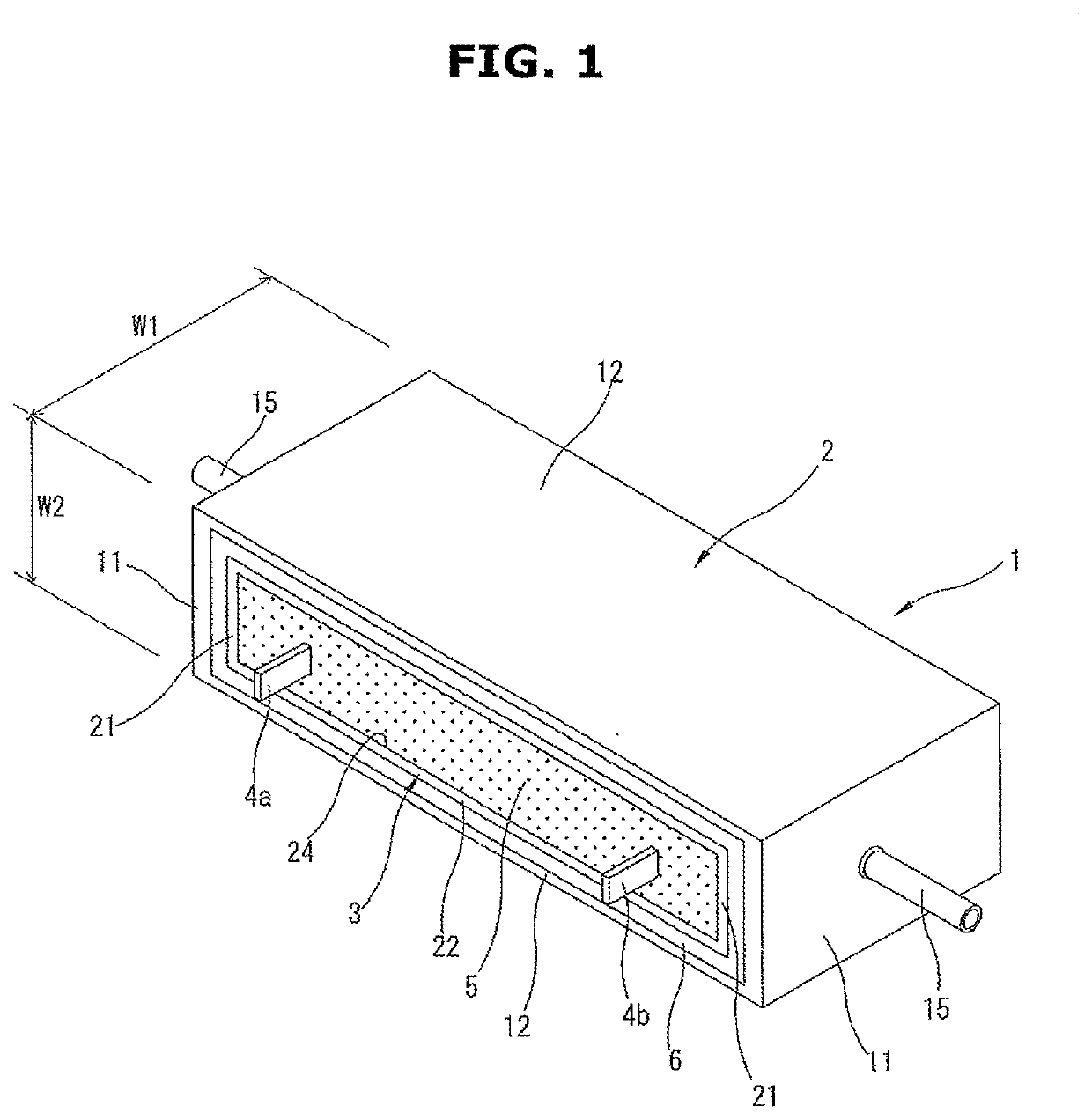
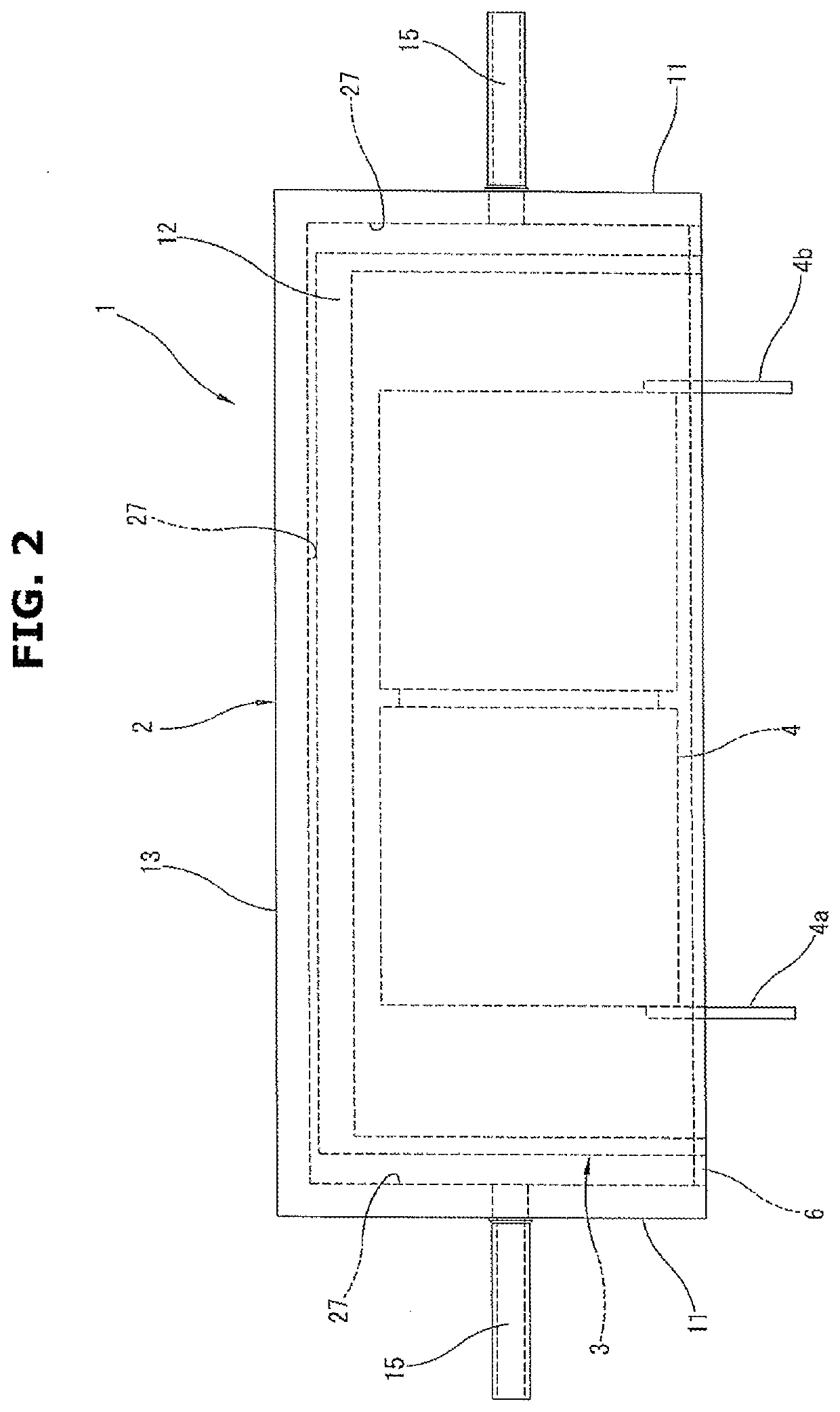
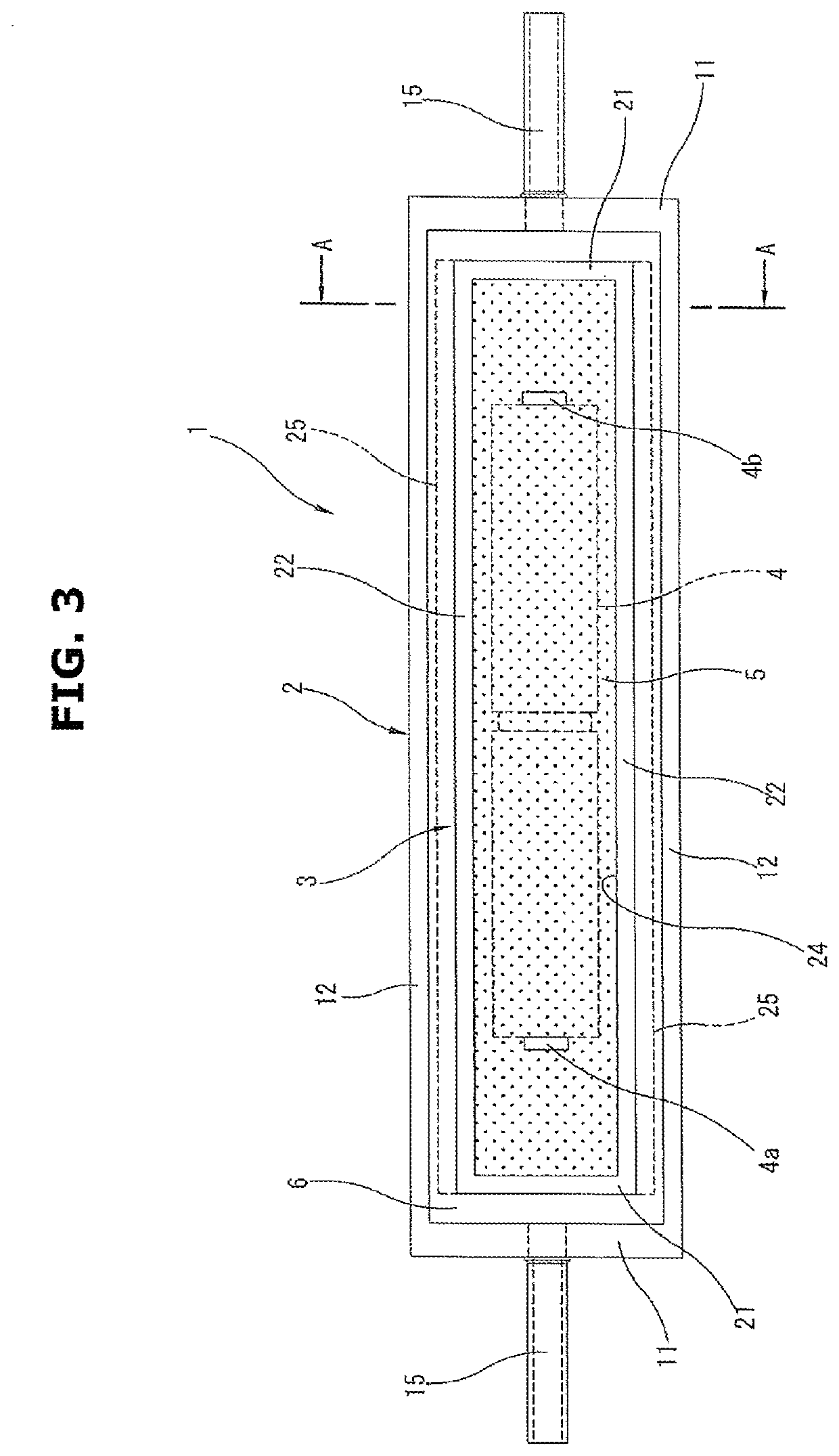
[0036]In the following description, embodiments of a capacitor 1 according to the present invention will be explained in detail with reference to the drawings.

[0037]FIG. 1 is a perspective view showing a first embodiment of the capacitor 1 used as a component forming an inverter for, for instance, an electric vehicle and a hybrid vehicle. FIG. 2 is a plan view of the capacitor 1 of the first embodiment. FIG. 3 is a front view of the capacitor 1 of the first embodiment. FIG. 4 is a sectional view taken along an A-A line of FIG. 3. The capacitor 1 has an outer case 2 having a rectangular parallelepiped shape, as shown in FIG. 4, an inner case 3 having a similar rectangular parallelepiped shape and accommodated in the outer case 2, a capacitor element 4 placed in the inner case 3 and potting material 5 filling the inner case 3 and cured so that the capacitor element 4 is embedded. FIG. 5 is a perspective exploded view showing the outer case 2, the inner case 3 and the capacitor element...


PUM


Abstract

A box-shaped inner case (3) is accommodated in a box-shaped outer case (2), and refrigerant flow passages (27) are formed at five surfaces except opening surfaces (14, 24) by gaps between the inner and outer cases. A Gap of an opening edge of the outer case (2) and an opening edge of the inner case (3) is covered with a frame-shaped cover (6). A capacitor element (4) formed from a film capacitor is placed in the inner case (3), and the inner case (3) is filledwithpottingmaterial (5) having thermal conductivity so that the capacitor element (4) except the terminals (4a, 4b) is embedded. Cooling water flows along a longitudinal direction of the outer case (2) with one of refrigerant pipe connecters (15) being a refrigerant inlet and the other of the refrigerant pipe connecters (15) being a refrigerant outlet.

Description

TECHNICAL FIELD[0001]The present invention relates to a capacitor used for a power conversion device etc., and more particularly to a capacitor having a cooling mechanism.BACKGROUND ART[0002]As one of components forming a power conversion device such as an inverter, a capacitor is used. Although, for size reduction of the power conversion device, there is a need to reduce sizes of the components forming the power conversion device, in order to reduce a size of the capacitor as a typical component forming the power conversion device, it is necessary to efficiently cool the capacitor that is a component having relatively low heat resistance. Especially in a case where temperature (ambient temperature) of a surrounding atmosphere exceeds heat resistant temperature of the capacitor in an environment in which the capacitor is used, some active cooling is needed.[0003]Patent Document 1 discloses an inverter device in which a cooling water flow passage is formed inside a wall portion of a ...

Claims


Application Information

Patent Timeline
Patent Type & Authority Applications(United States)
IPC IPC(8): H01G4/258H01G4/224H01G4/40
CPCH01G4/258H01G4/40H01G4/224H01G2/08H01G4/236H01G2/04
Inventor KODACHI, KEIICHIYAMAMOTO, YUKATEY, KUAN CHUNG
Owner MEIDENSHA ELECTRIC MFG CO LTD
Why Eureka
Try Eureka