Electronic device
- Summary
- Abstract
- Description
- Claims
- Application Information
AI Technical Summary
Benefits of technology
Problems solved by technology
Method used
Image
Examples
embodiment 1
Preferred Embodiment 1
(1) Overall Configuration of Electronic Device
[0022]An overall configuration of an electronic device according to Preferred Embodiment 1 will be described with reference to the drawings.
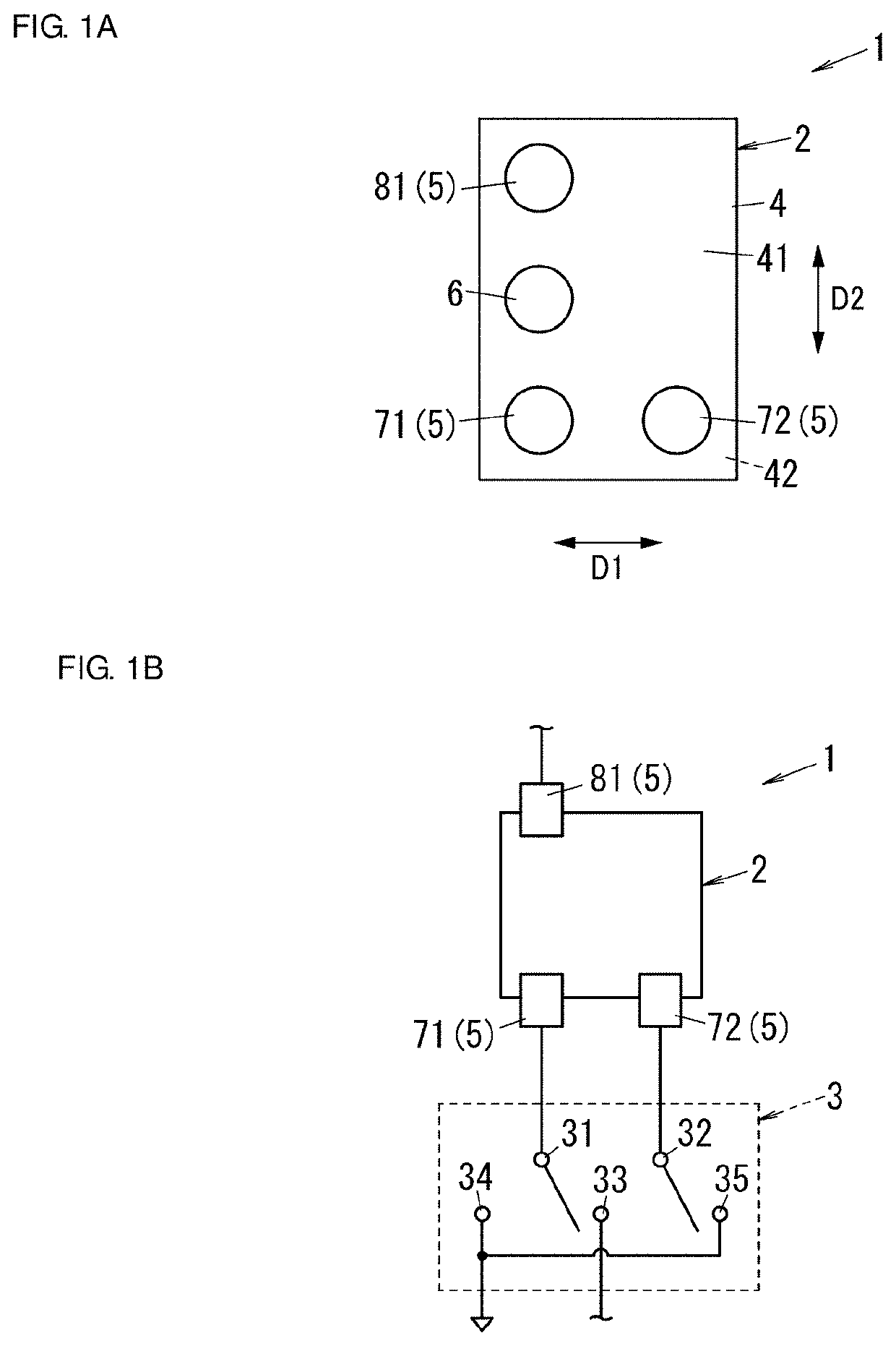
[0023]An electronic device 1 includes an electronic component 2, a switch 3, and a wiring substrate 11 (see FIG. 2) as illustrated in FIGS. 1A and 1B. The electronic device 1 is used for radio frequency signal processing, for example, in the communication field.
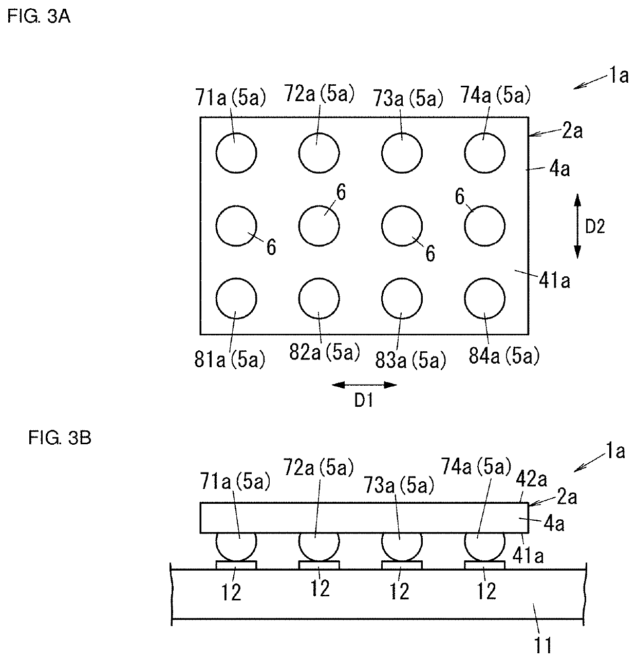
[0024]The wiring substrate 11 may be a motherboard of the electronic device 1 or may be a wiring structure having a module structure, for example. The wiring substrate 11 is provided with a plurality of pads 12 (see FIG. 3B).
(2) Each Element of Electronic Device
[0025]Hereinafter, elements of the electronic device 1 will be described with reference to the drawings.
(2.1) Electronic Component
[0026]The electronic component 2 includes a plurality of circuits (not illustrated) that function independently of one another. The ele...
embodiment 2
Preferred Embodiment 2
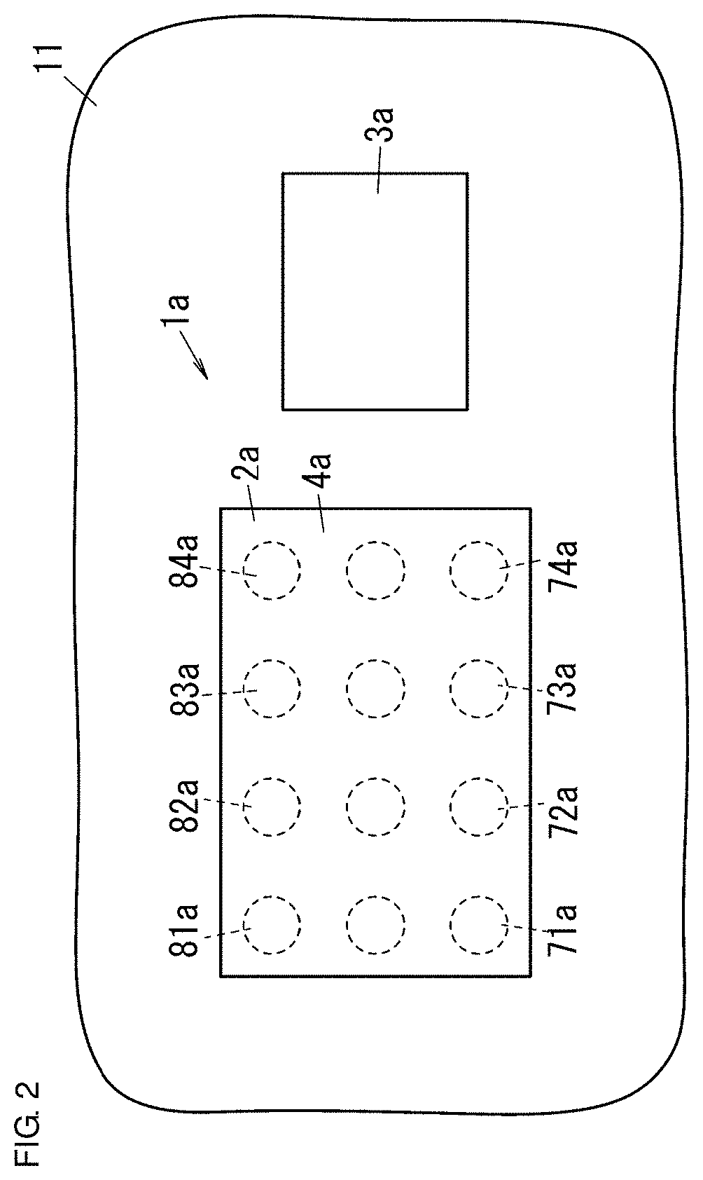
[0053]An electronic device 1a according to Preferred Embodiment 2 is different from the electronic device 1 according to Preferred Embodiment 1 (see FIG. 1B) in that four first input / output terminals 71a to 74a and four second input / output terminals 81a to 84a are provided to a base body 4a as illustrated in FIG. 2.
(1) Overall Configuration of Electronic Device
[0054]The electronic device 1a includes an electronic component 2a and a switch 3a as illustrated in FIG. 2. Note that, with respect to the electronic device 1a, the same elements as those of the electronic device 1 according to Preferred Embodiment 1 are denoted by the same reference numerals, and the description thereof will be omitted.
(2) Each Element of Electronic Device
[0055]Hereinafter, each element of the electronic device 1a will be described with reference to the drawings.
(2.1) Electronic Component
[0056]The electronic component 2a includes the base body 4a, eight input / output terminals 5a, and th...
embodiment 3
Preferred Embodiment 3
[0077]An electronic device 1b according to Preferred Embodiment 3 is different from the electronic device 1a according to Preferred Embodiment 2 (see FIGS. 3A and 3B) in that eight input / output terminals 5b are provided to a second main surface 42b of a base body 4b and a plurality of (eight in illustrated example) electrical connection portions 9 are provided to a side surface 43 of the base body 4b as illustrated in FIGS. 5A and 5B.
[0078]The electronic device 1b includes, as illustrated in FIGS. 5A and 5B, an electronic component 2b and the switch 3a (see FIG. 4). The electronic device 1b is mounted on the wiring substrate 11. Note that, with respect to the electronic device 1b, the same elements as those of the electronic device 1a according to Preferred Embodiment 2 are denoted by the same reference numerals, and the description thereof will be omitted.
[0079]The electronic component 2b includes the base body 4b, the eight input / output terminals 5b, and four...
PUM
 Abstract
Description
Claims
Application Information
 - R&D
- Intellectual Property
- Life Sciences
- Materials
- Tech Scout
- Unparalleled Data Quality
- Higher Quality Content
- 60% Fewer Hallucinations
Browse by: Latest US Patents, China's latest patents, Technical Efficacy Thesaurus, Application Domain, Technology Topic, Popular Technical Reports.
© 2025 PatSnap. All rights reserved.Legal|Privacy policy|Modern Slavery Act Transparency Statement|Sitemap|About US| Contact US: help@patsnap.com


