Storage control device, storage device, and storage control method
a storage control and control device technology, applied in the field of storage control devices, can solve the problems of erroneous determination of the resistance state of the variable resistance unit, drift may occur, etc., and achieve the effect of eliminating drift generated in a memory cell, continuing use of memory cells, and excellent
- Summary
- Abstract
- Description
- Claims
- Application Information
AI Technical Summary
Benefits of technology
Problems solved by technology
Method used
Image

Examples
first embodiment
1. First Embodiment
[Configuration of Information Processing System]
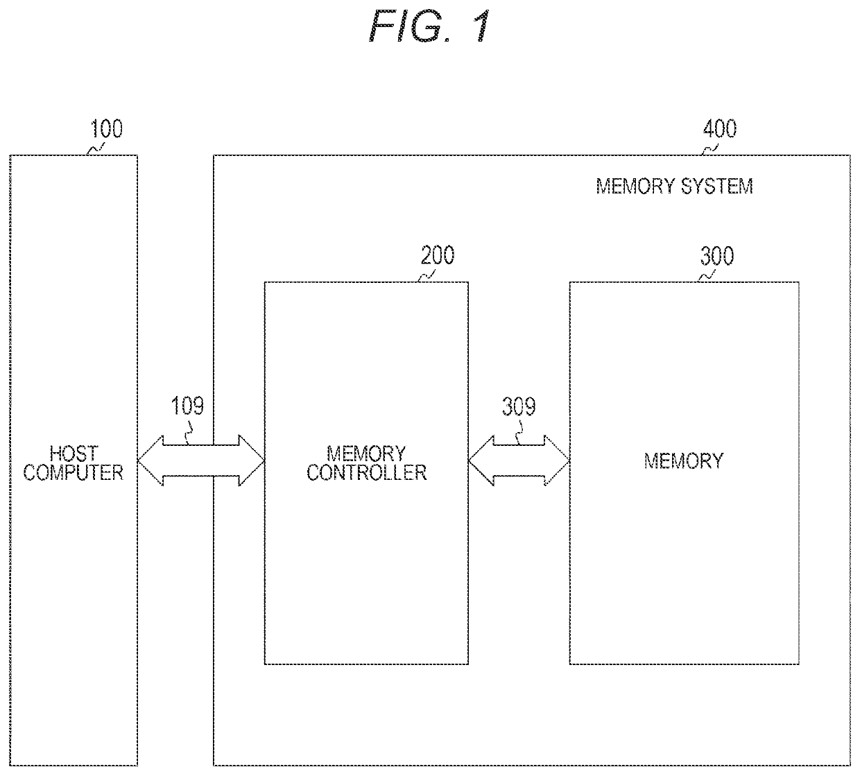
[0050]FIG. 1 is a diagram showing a configuration example of an information processing system of an embodiment of the present technology. The information processing system includes a host computer 100, a memory controller 200, and a memory 300. A memory system 400 includes the memory controller 200 and the memory 300.
[0051]The host computer 100 issues commands to the memory 300 to give an instruction on data read processing, data write processing, and the like. The host computer 100 includes a processor that executes processing as the host computer 100, and a controller interface for exchanging information with the memory controller 200. A signal line 109 connects the host computer 100 and the memory controller 200.
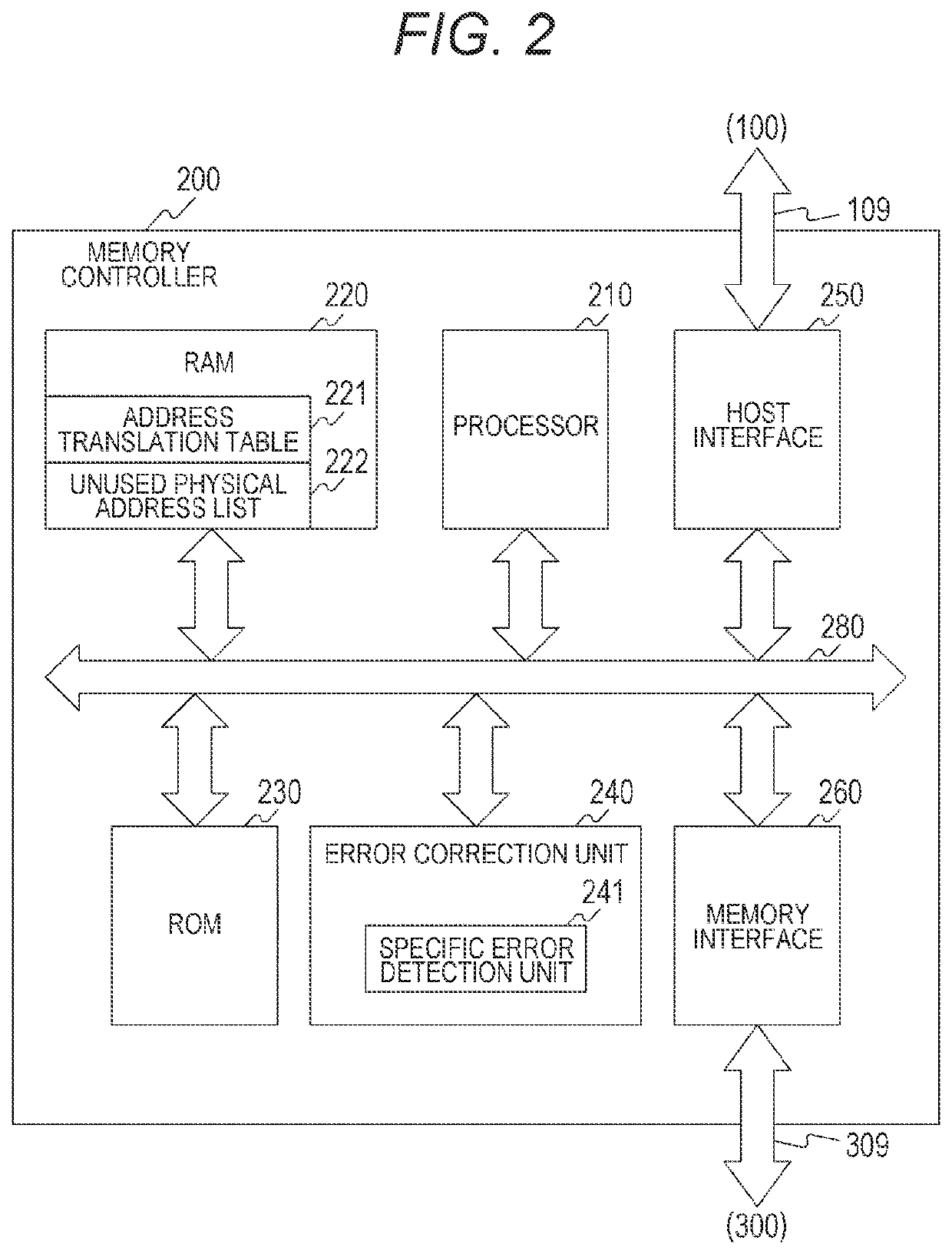
[0052]The memory controller 200 controls a request for the memory 300 according to a command from the host computer 100. A signal line 309 connects the memory controller 200 and the memory 300.
[0053]The me...
second embodiment
2. Second Embodiment
[0175]In the first embodiment described above, the error-corrected data is written to a new area (unused physical address). However, in this second embodiment, it is assumed that the original area (physical address) where a drift refresh is executed is used as it is. Note that since the configuration of the information processing system is similar to that of the first embodiment described above, detailed description thereof will be omitted.
[Operation]
[0176]FIG. 22 is a flow chart showing an example of a processing procedure of drift refresh processing of a memory controller 200 of the second embodiment of the present technology. The drift refresh processing of the memory controller 200 of the second embodiment corresponds to the processing in step S830 of the first embodiment described above.
[0177]A processor 210 specifies a physical address determined by a specific error detection unit 241 that a specific error has occurred, and makes a drift refresh request to ...
third embodiment
3. Third Embodiment
[0181]In the first embodiment described above, “Vread311. In this third embodiment, “Vdr=Vreset”. That is, a pulse having the same voltage as the reset pulse is used as the drift refresh pulse. With this configuration, the drift refresh control unit 353 can be shared with the program control unit 351, and the circuit for generating the drift refresh pulse can be reduced. Note that since other parts of the configuration of the information processing system are similar to those of the first embodiment described above, detailed description thereof will be omitted.
[Buffer]
[0182]FIG. 23 is a diagram showing an example of a buffer held in an access buffer 370 after verification processing in the third embodiment of the present technology.
[0183]In the third embodiment, drift refresh processing is performed on a memory cell 311 in a low resistance state (LRS). A drift refresh pulse Vdr at this time has the same voltage as a reset pulse Vreset. Accordingly, the memory cell...
PUM
 Abstract
Description
Claims
Application Information
 - R&D
- Intellectual Property
- Life Sciences
- Materials
- Tech Scout
- Unparalleled Data Quality
- Higher Quality Content
- 60% Fewer Hallucinations
Browse by: Latest US Patents, China's latest patents, Technical Efficacy Thesaurus, Application Domain, Technology Topic, Popular Technical Reports.
© 2025 PatSnap. All rights reserved.Legal|Privacy policy|Modern Slavery Act Transparency Statement|Sitemap|About US| Contact US: help@patsnap.com