
Flocculation state monitoring sensor

Active Publication Date: 2021-08-26
KURITA WATER INDUSTRIES LTD
View PDF12 Cites 0 Cited by
  • Summary
  • Abstract
  • Description
  • Claims
  • Application Information

AI Technical Summary

Benefits of technology

The present invention provides a sensor that monitors the flocculation state during a cleaning process. The sensor prevents the formation of particles and ensures that the light emitting and receiving parts are adequately cleaned. This is achieved by supplying a small amount of air to the ejecting part and purging water or floc during the cleaning periods. The sensor reduces the air supply time to the ejecting part and prevents residual air from strongly impacting the light emitting and receiving parts. Furthermore, the short purging period does not significantly reduce the measuring period of the sensor.

Problems solved by technology

Accordingly, cleaning of the light emitting part and the light receiving part is insufficient.
In order to discharge the flocculated particles from the ejecting part, when an air ejecting pressure is increased during cleaning, the ejected air or gas-liquid mixed phase flow strongly abuts the light emitting part or the light receiving part, and the light emitting part or the light receiving part may be damaged.

Method used


Image

  • Flocculation state monitoring sensor

Examples


Embodiment Construction

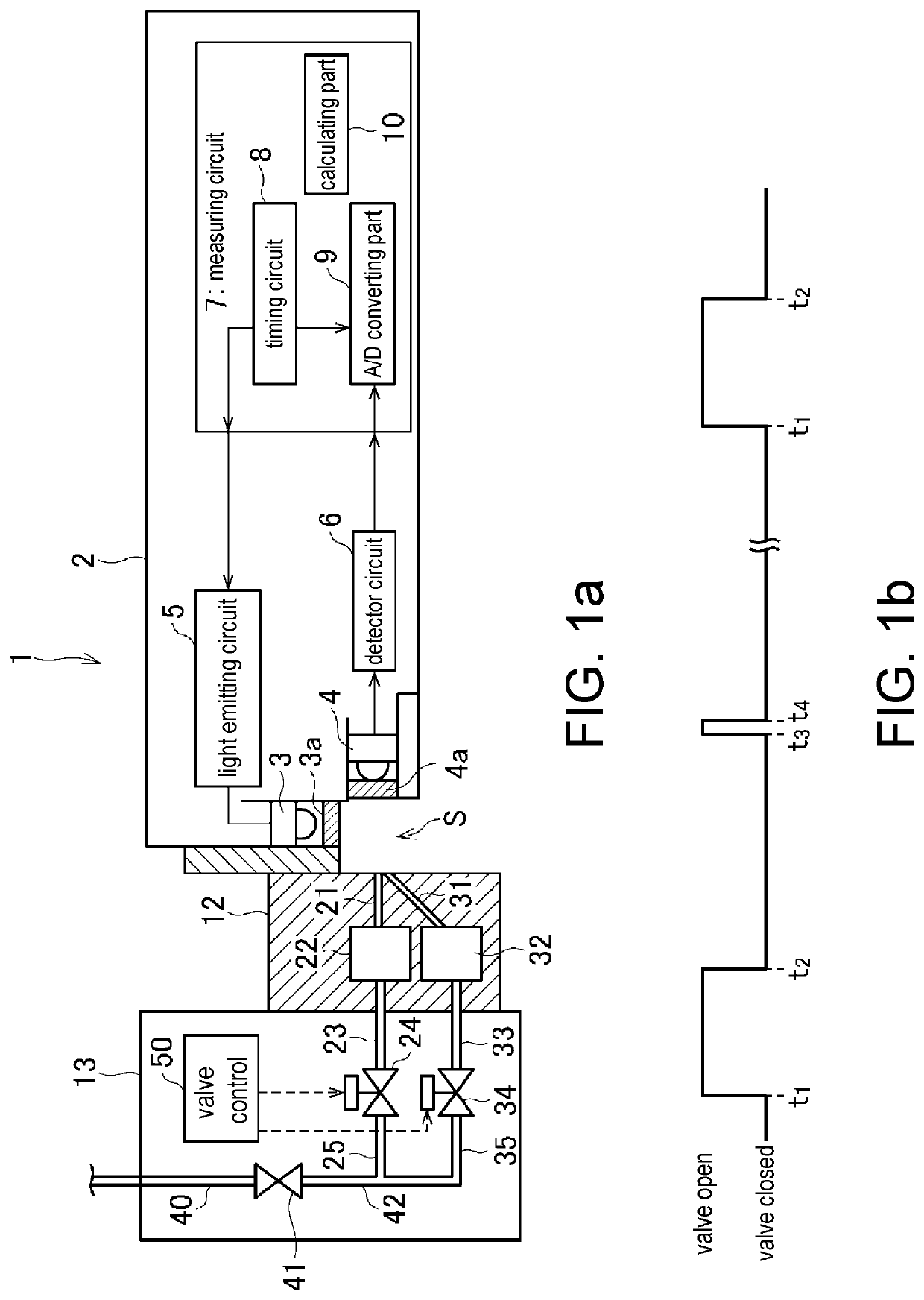
[0015]Hereinafter, an embodiment will be described with reference to FIGS. 1a and 1b.

[0016]A probe 1 that constitutes a flocculation state monitoring sensor has a light emitting part 3 disposed on a tip side of a casing 2 and configured to radiate laser light toward a measuring region S of a flocculation processing liquid (a liquid to which flocculant is added and which is stirred according to necessity). In addition, a light receiving part 4 using a light receiving optical axis in a direction perpendicular to a light receiving optical axis of the light emitting part 3 is provided to face the measuring region S. Transparent plates 3a and 4a are provided on front surfaces of the light emitting part 3 and the light receiving part 4, respectively, and circumferential edge portions of the transparent plates 3a and 4a are sealed water-tightly.

[0017]A light emitting circuit 5, a detector circuit 6 and a measuring circuit 7 are provided in the probe 1. The measuring circuit 7 has a timing...


PUM

PropertyMeasurementUnit
Timeaaaaaaaaaa
Frequencyaaaaaaaaaa
Flocculationaaaaaaaaaa

Abstract

Provided is a flocculation state monitoring sensor with which blockage of an ejecting part which ejects a gas towards a light emitting part and a light receiving part can be prevented, and which performs stable monitoring. A flocculation state monitoring sensor comprising: a light emitting part which irradiates laser light towards a measuring region which measures a flocculation state; and a light receiving part which receives light scattered along a direction which intersects with a direction along an optical axis of said light emitting part, wherein the light emitting part and the light receiving part are cleaned by air being ejected from nozzles theretowards. A small amount of air is provided to the nozzles between cleaning periods to purge floc, etc.

Description

TECHNICAL FIELD[0001]The present invention relates to a flocculation state monitoring sensor configured to measure a flocculation state in a flocculation processing liquid, and more particular, to a flocculation state monitoring sensor configured to measure a flocculation state by radiating light into water and receiving scattered light.BACKGROUND ART[0002]Patent Literature 1 discloses a flocculation state monitoring sensor configured to measure a flocculation state by emitting laser light toward water and receiving scattered light scattered by a floc or the like in the water.[0003]Since the flocculation state monitoring sensor uses light such as laser or LED in detection, it is important to secure an optical path of the light, and for this reason, cleaning is intermittently needed to remove SS elements adhered to a light emitting part or a light receiving part.[0004]In order to perform the cleaning, air is ejected from an ejecting part toward the light emitting part and the light r...

Claims


Application Information

Patent Timeline
IPC IPC(8): G01N21/53G01N21/51G01N15/06
CPCG01N21/532G01N21/51G01N2015/0693G01N2021/513G01N15/06G01N21/53G01N21/15G01N2021/151G01N21/82B03D3/06B01D21/32B08B5/02G01N15/075
Inventor NAGAO, NOBUAKI
Owner KURITA WATER INDUSTRIES LTD
Learn More