Assembly for Detecting the Intensity Distribution of Components of the Electromagnetic Field in Beams of Radiation

a technology of electromagnetic field and intensity distribution, applied in the direction of optical radiation measurement, instruments, spectrometry/spectrophotometry/monochromators, etc., can solve the problems of reducing intensity, arrays are not suitable, and separation according to vector components is only possible in x, so as to achieve the effect of increasing resolution

Active Publication Date: 2021-08-26
JANUNTS NORIK
View PDF0 Cites 4 Cited by
  • Summary
  • Abstract
  • Description
  • Claims
  • Application Information

AI Technical Summary

Benefits of technology

[0035]A particular advantage of the invention consists in that a high-resolution field vector detector array can be combined with all conventional intensity-measuring photosensor arrays (CCD, CMOS, FPA, etc.) and voltage-measuring detector arrays (Schottky diode array, thermocouple array, microbolometer array, etc.).
[0036]Further, the field vector detector array according to the invention can be assembled in a structured manner in accordance with the Bayer color filter mask principle (or also CYGM or CMYW or Sony RGBE, etc.) from four-pixel elements or from quadrant regions with the field vector components (with or without reference struct

Problems solved by technology

However, separation according to vector components is only possible in x-direction and y-direction.
However, for each vector component, only amplitude measurements or phase measurements of the intensity are possible, or beam splitters are required which further diminish intensity.
The drawback here consists in that with such small incident angles the disclosed sensor array is not suitable for highly focused beams of radiation and—because of the lack of longitudinal polarization measurement—can only measure transverse polarization components.
This solution has the disadvantage that it is not usable for a recording resolved according to polarization directions because light is captured not only at the probe tip (apex) but also at the slits between the microstrips along the outer lateral surface of the cone and, therefore, the decisive s

Method used


Image

  • Assembly for Detecting the Intensity Distribution of Components of the Electromagnetic Field in Beams of Radiation
  • Assembly for Detecting the Intensity Distribution of Components of the Electromagnetic Field in Beams of Radiation
  • Assembly for Detecting the Intensity Distribution of Components of the Electromagnetic Field in Beams of Radiation

Examples


Embodiment Construction

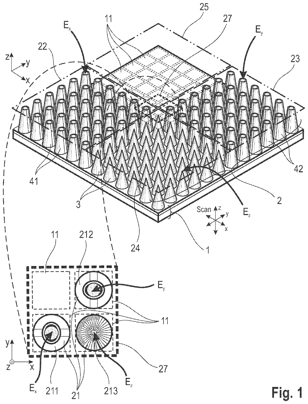
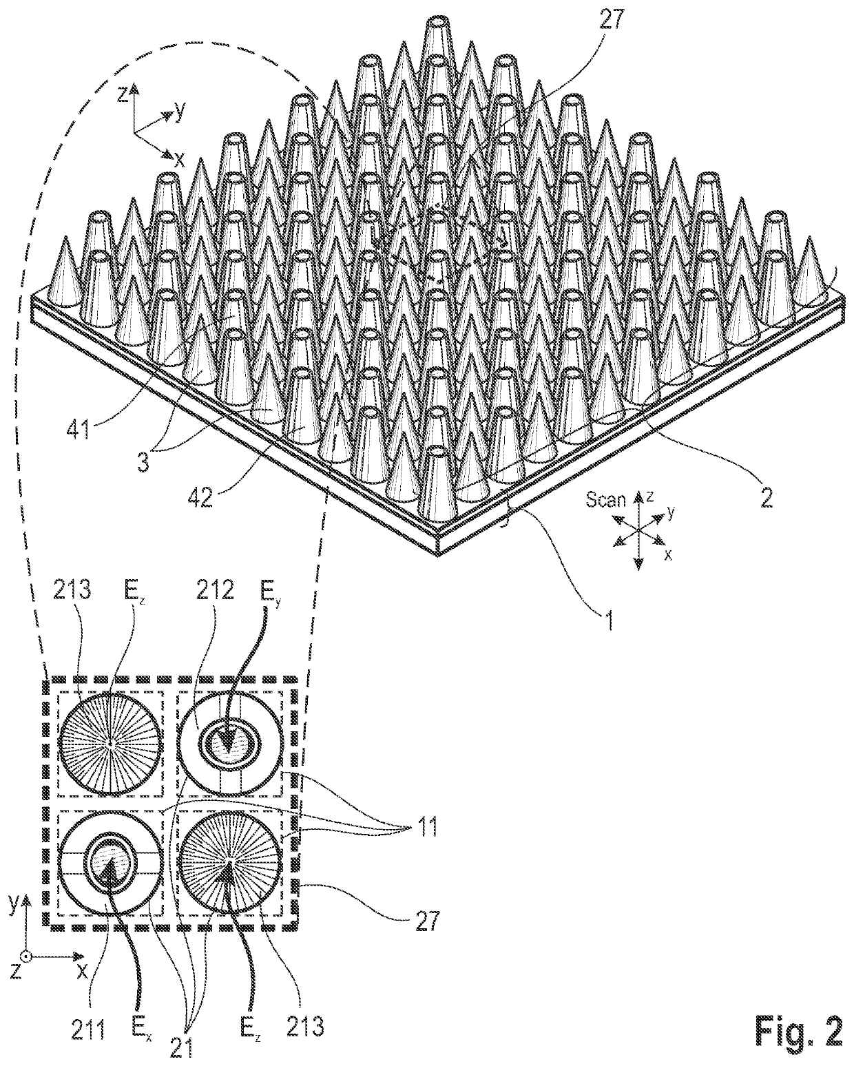
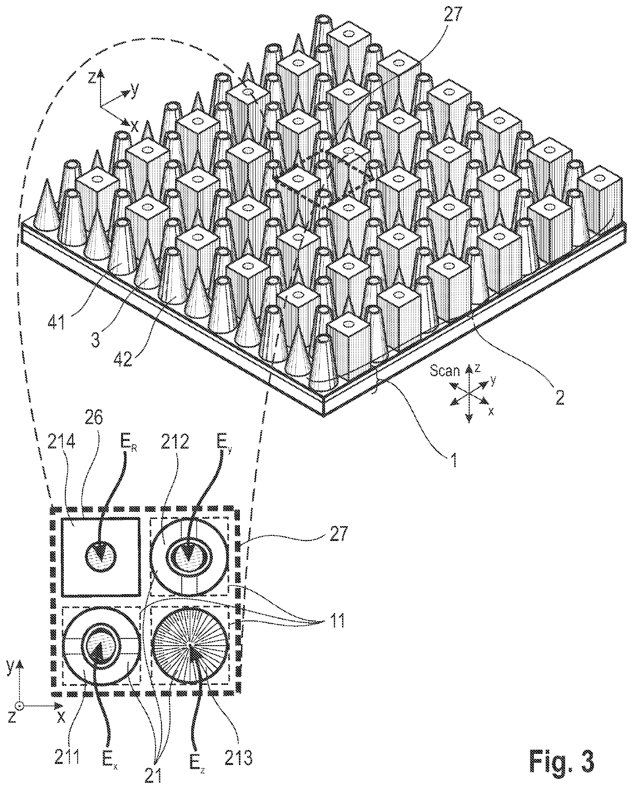
[0064]Referring to FIG. 1, the basic construction of an arrangement according to the invention comprises a two-dimensional intensity sensor array 1 and a field vector detector array 2 for the different field vector components as spatial arrangement of one structure each for separate detection of the three field vector components. The field vector detector array 2 is arranged above a two-dimensional intensity sensor array (CCD, CMOS, FPA, etc.) and the individual detector structures 21 are mapped to the sensor elements 11 of the intensity sensor array 1 so as to be matched with respect to the pixel grid. The mapping of the detector structures 21 to the sensor elements 11 is preferably carried out pixel-wise (i.e., in a 1-1 mapping), but can also be performed by groups of sensor elements 11 (e.g., 1 to 4, 1 to 9, etc.). An intensity sensor array 1 mapped group-wise in this way can be read out in an accelerated manner by binning such groups. The arrangement of the field vector detector...


PUM


Abstract

The invention is directed to an arrangement for detecting the intensity distribution of components of the electromagnetic field in beams of radiation. The object of the invention is met, according to the invention, in that a high-resolution two-dimensional intensity sensor array and a field vector detector array comprising different regions with individual detector structures for two transverse and longitudinal field vector components Ex, Ey, Ez are combined, wherein the detector structures are formed as nanostructures, metallic jacket-shaped tips with different apices, for utilization of localized plasmon resonance (LPR) of the individual detector structures and localized surface plasmons (LSP) excited through LPR for a polarization selection of the field distribution according to field vector components Ex, Ey, Ez and transmission thereof to associated sensor elements by means of surface plasmon polaritons (SPP) and wave guiding (WGM).

Description

RELATED APPLICATIONS[0001]This Application is a U.S. National Stage Under 35 USC § 371 of International Application PCT / DE2019 / 100706, filed on Aug. 2, 2019, which in turn claims priority to German Patent Application DE 10 2018 119 096.4, filed Aug. 6, 2018, both of which are incorporated herein by reference in their entirety.FIELD OF THE INVENTION[0002]The invention is directed to an arrangement for the detection of the intensity distribution of components of the electromagnetic field in beams of radiation, preferably for the selective measurement of the field vector distribution for assessing the beam quality of radiation sources or for the analysis and evaluation of the point spread function (PSF) or modulation transfer function (MTF) of optics and other optical elements.BACKGROUND OF THE INVENTION[0003]Light, as electromagnetic wave, is characterized by its vector field which can in turn be defined by three (Cartesian) components in space and by the amplitude and phase position ...

Claims


Application Information

Patent Timeline
IPC IPC(8): G01Q60/22G01J1/04G01J1/42G01J3/02G01J4/04G01Q70/06G02B6/42
CPCG01Q60/22G01J1/0429G01J1/4257G02B6/4298G01J4/04G01Q70/06G01J3/0224G02B6/1226G02B6/08G01J4/00G01J9/00G01J4/02
Inventor JANUNTS, NORIK
Owner JANUNTS NORIK
Why Eureka
Try Eureka