
Resonant cavity surface acoustic wave (SAW) filters

Pending Publication Date: 2021-08-26
FRECNSYS
View PDF0 Cites 0 Cited by
  • Summary
  • Abstract
  • Description
  • Claims
  • Application Information

AI Technical Summary

Benefits of technology

The patent aims to address previous issues by designing a surface acoustic wave (SAW) filter device on a composite substrate that is more compact, simple, versatile, and performs well. The technical effects of this invention include improved design for smaller size, easier use, and better performance of the SAW filter device.

Problems solved by technology

However, the use of classical filter structures in SAW devices faces various problems, such as compactness and performance of the device.
However, the use of piezoelectric substrates leads to either high sensibility to temperature or weak electromechanical coupling depending on the piezoelectric material used.
This results in poor performance of the filters' pass-band characteristics.
However, these approaches generally allow for two or more poles to be placed in the passband, thus resulting in non-optimized performance of the device and need a relatively large footprint.

Method used


Image

  • Resonant cavity surface acoustic wave (SAW) filters
  • Resonant cavity surface acoustic wave (SAW) filters
  • Resonant cavity surface acoustic wave (SAW) filters

Examples


first embodiment

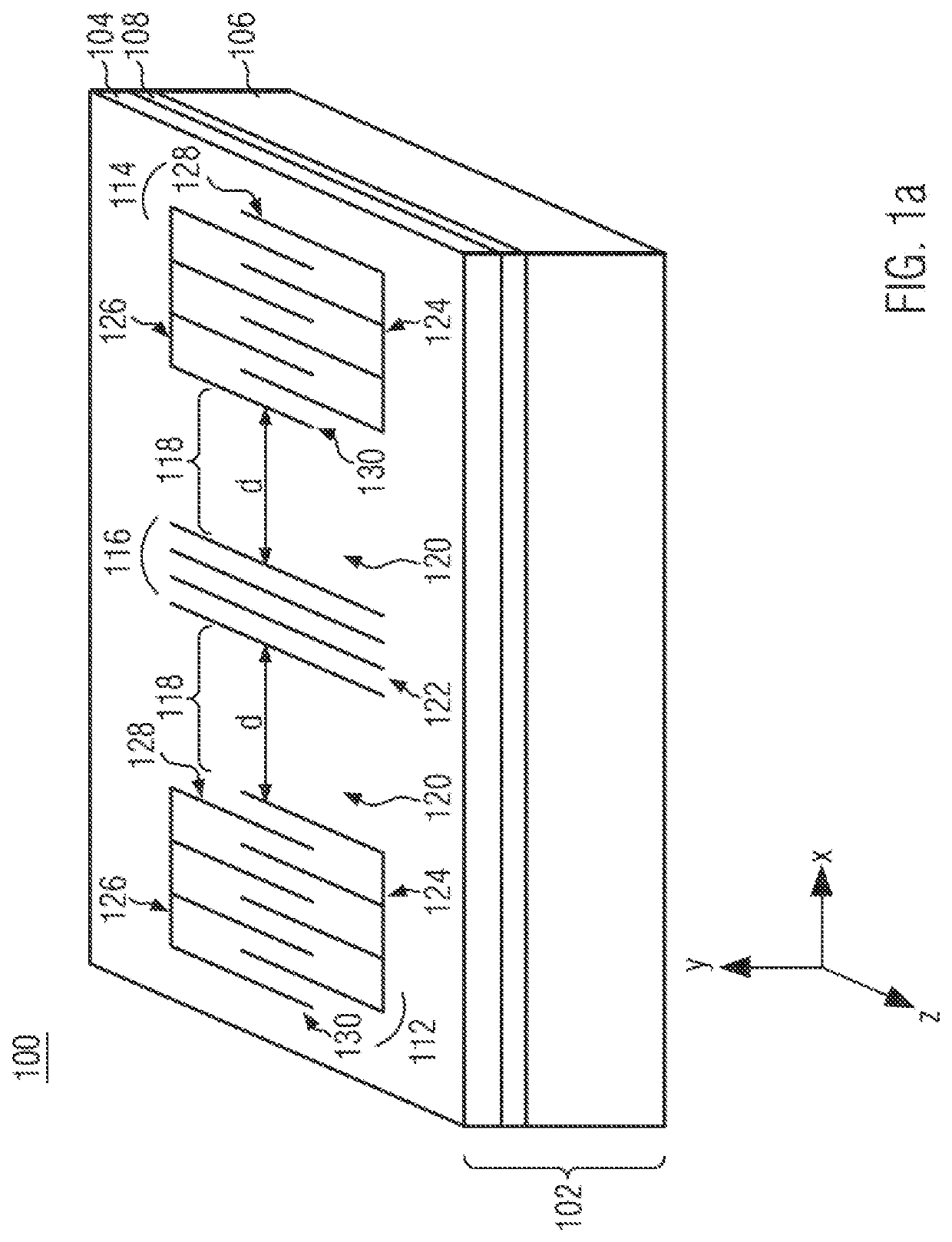
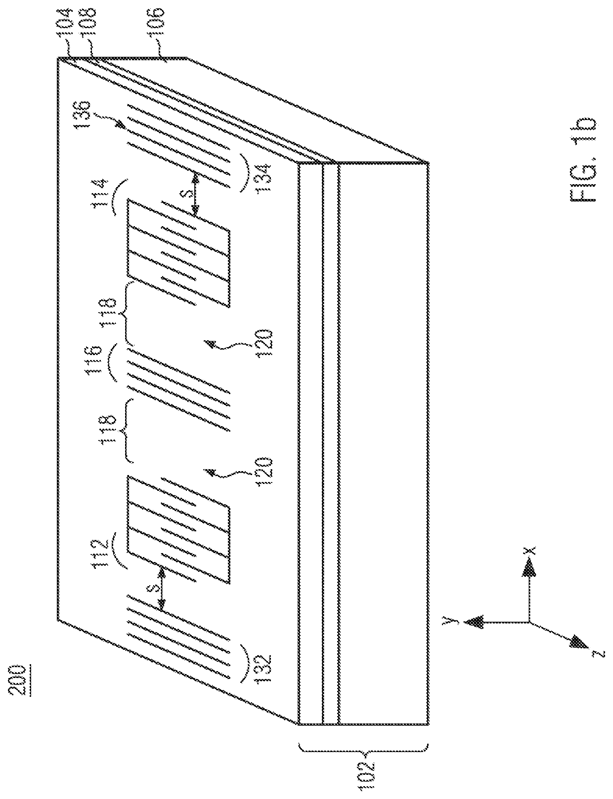
[0060]FIG. 1 shows a coupled cavity surface acoustic wave filter structure according to the disclosure. In FIG. 1a, the coupled cavity surface acoustic wave filter structure 100 is realized on a substrate 102, being a composite substrate. The composite substrate 102 comprises a layer of piezoelectric material layer 104, with crystallographic axis X, Y and Z, formed over a base substrate 106.

[0061]The piezoelectric material layer 104 in this embodiment is LiTaO3 or LiNbO3, particularly with cut orientations defined by (YXl) / θ according to the standard IEEE 1949 Std-176, with θ, an angle of the crystallographic orientation being comprised between 0° and 60° or between 90° and 150°, Potassium Niobate KNbO3 and similar material composition such as KTN, as well as other piezoelectric layers using sputtered or epitaxial films, for instance, Aluminum Nitride AlN, Zinc Oxide ZnO, PZT, GaN or any composition of AlN and GaN.

[0062]The thickness of the piezoelectric material layer 104 formed on...

second embodiment

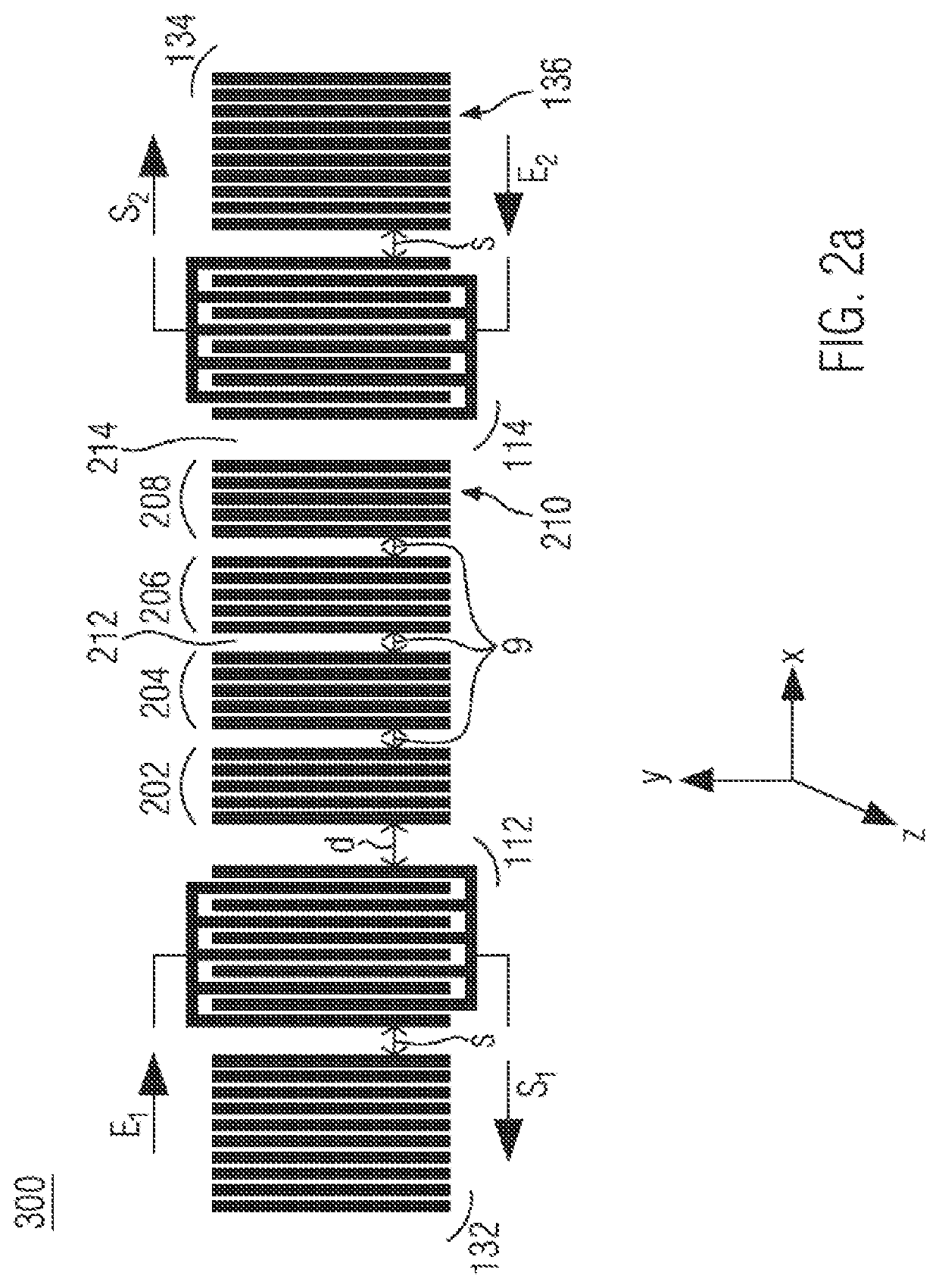
[0082]FIGS. 2a to 2e show the coupled cavity filter structure according to the disclosure and its variants. For all the FIGS. 2a to 2e, the coupled cavity filter structure is shown in a 2D plan view and the substrate on which it is positioned is not shown anymore. However, the substrate is the same as the substrate 102 of FIGS. 1a, 1b. The same reference numbers as in FIGS. 1a and 1b will be used to refer to the same features and will not be explained again in details.

[0083]In FIG. 2a, the coupled cavity filter structure 300 comprises, like the coupled cavity filter structure 200, two transducer structures 112, 114 with two Bragg mirrors 132, 134, each positioned next to one transducer structure. The difference with the coupled cavity filter 200 is that a plurality of reflecting structures, namely four reflecting structures 202, 204, 206, 208, are present in between the transducer structures 112, 114. Each reflecting structure 202, 204, 206, 208 of the plurality of reflecting struct...

third embodiment

[0117]FIGS. 5a and 5b illustrate a coupled cavity surface acoustic wave filter structure according to the disclosure.

[0118]In the third embodiment, like for the first embodiment shown in FIGS. 1a and 1b, the coupled cavity surface acoustic wave filter structure 800 is realized on a composite substrate 102 being the same as the substrate 102 of FIGS. 1a and 1b.

[0119]The same reference numbers as in FIGS. 1a and 1b will be used to refer to the same features and will not be explained again in details.

[0120]In this embodiment, the thin SiO2 layer 108 provided at the interface 110 between the piezoelectric material layer 104 and the base substrate 106 to improve the attachment of the piezoelectric material layer 104 to the base substrate 106 is 500 nm thick.

[0121]The coupled cavity filter structure 800 comprises two transducer structures 812, 814 and one reflecting structure 816, positioned between the two transducer structures 812, 814 at a certain distance L of the transducer structur...


PUM


Abstract

A coupled cavity filter structure that uses a surface acoustic wave, in particular, a guided surface acoustic wave, comprises an acoustic wave propagating substrate, at least one input transducer structure and one output transducer structure, provided over the substrate, each comprising inter-digitated comb electrodes, at least one reflecting structure comprising at least one or more metallic strips, positioned at a distance and in between the input and output transducer structures, in the direction of propagation of an acoustic wave. The acoustic wave propagating substrate is a composite substrate comprising a base substrate and a piezoelectric layer. In additional embodiments, a coupled cavity filter structure comprises a groove. In additional embodiments, a SAW ladder filter device comprises at least two coupled cavity filter structures as described herein, wherein the at least two coupled cavity filter structures are positioned on a single line.

Description

CROSS-REFERENCE TO RELATED APPLICATIONS[0001]This application is a national phase entry under 35 U.S.C. § 371 of International Patent Application PCT / EP2019 / 070082, filed Jul. 25, 2019, designating the United States of America and published in English as International Patent Publication WO 2020 / 021029 A2 on Jan. 30, 2020, which claims the benefit under Article 8 of the Patent Cooperation Treaty to European Patent Application Serial No. 18306023.5, filed Jul. 27, 2018, and to European Patent Application Serial No. 19305956.5, filed Jul. 18, 2019.TECHNICAL FIELD[0002]This disclosure relates to surface acoustic wave devices for filter applications and, more particularly, to a composite substrate for surface acoustic wave filter devices.BACKGROUND[0003]In recent years, surface acoustic wave (SAW) devices have been employed in an increasing number of practical applications, such as filters, sensors and delay lines.[0004]The synthesis of SAW filters requires different types of tools and a...

Claims


Application Information

Patent Timeline
IPC IPC(8): H03H9/64H03H9/02
CPCH03H9/6483H03H9/6489H03H9/02669H03H9/02724H03H9/02771H03H9/02905H03H9/02803H03H9/02811H03H9/643
Inventor BALLANDRAS, SYLVAINLAROCHE, THIERRY
Owner FRECNSYS
Features
  • Generate Ideas
  • Intellectual Property
  • Life Sciences
  • Materials
  • Tech Scout
  • Unparalleled Data Quality
  • Higher Quality Content
  • 60% Fewer Hallucinations
Learn More