High bandwidth ultrasonic transducer with metal backing layer and method of fabrication

a technology of ultrasonic transducers and backing layers, which is applied in piezoelectric/electrostrictive/magnetostrictive devices, mechanical vibration separation, electrical equipment, etc., can solve the problems of difficult mixing of epoxy and achieve high damping. , high acoustic impedance, high acoustic energy loss

Pending Publication Date: 2021-09-16
ASCENT VENTURES LLC
View PDF0 Cites 2 Cited by
  • Summary
  • Abstract
  • Description
  • Claims
  • Application Information

AI Technical Summary

Benefits of technology

[0010]The present invention includes a wafer-level method of fabricating a backing layer that provides a high level of damping through a high acoustic impedance, has a high acoustic energy loss, and hence scatters, diffuses, and / or absorbs the backward traveling acoustic waves. According to the wafer-level method of fabricating, the backing layer can be manufactured with consistent device-to-device performance at a low manufacturing cost.

Problems solved by technology

While epoxy laden with metal particles may work as a damping material, the production of this epoxy with a uniform and consistent high acoustic impedance is difficult.
Getting to the high metal loading required for very high impedances and hence bandwidths tends to make the epoxy difficult to mix.
The heavy, metal particles settle, interfering with uniformity.
Air often becomes embedded in the mixture resulting in non-uniform air pockets of low acoustic impedance.
The higher the desired frequency of the transducer the smaller the particle size needed, exacerbating the aforementioned difficulties.
In addition, the value of acoustic impedance achieved by the epoxy is often very sensitive to the metal particle concentration in the mixture resulting in variation from batch to batch.
However, as the frequency increases, the required pore size reduces, making fabrication difficult and costly.
Further, sufficient acoustic coupling of this backing material to the piezoelectric material becomes difficult as the frequency increases.
Such device configurations and fabrication are not suitable to low cost, consistent performance, wafer-level production.

Method used


Image

  • High bandwidth ultrasonic transducer with metal backing layer and method of fabrication
  • High bandwidth ultrasonic transducer with metal backing layer and method of fabrication
  • High bandwidth ultrasonic transducer with metal backing layer and method of fabrication

Examples


Embodiment Construction

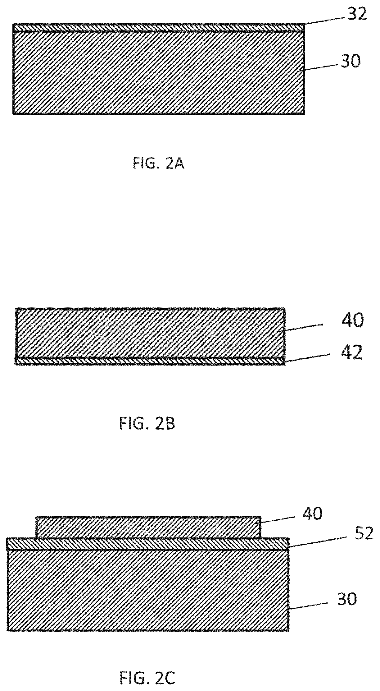
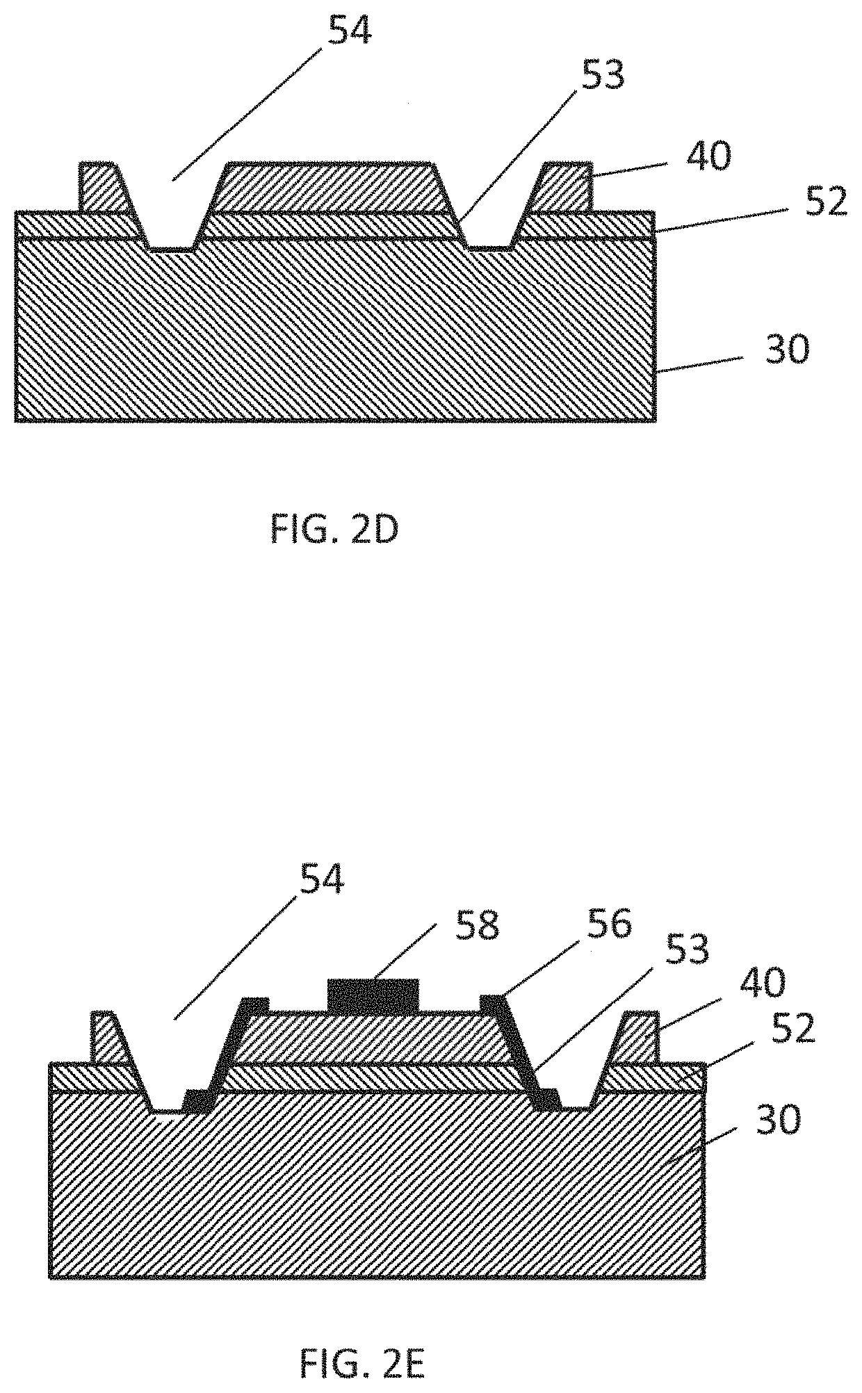
[0028]Similar to approaches employed in the semiconductor or MEMS industry, transducers can be produced using wafer-level processes to achieve fabrication and device consistency and cost reduction. A method of fabricating ultrasonic transducers, including the backing layer, using wafer-level processes, provides a potential for the highest device-to-device consistency and the lowest manufacturing cost. Accordingly, to overcome common issues with current high-frequency transducer backing layers and to significantly enhance transducer performance, consistency, and reliability, as well as lower the transducer manufacturing cost, a wafer-level method of fabricating a transducer is employed, including fabrication of a backing layer to significantly dampen the transducer response resulting in a high bandwidth transducer.

[0029]FIGS. 2A-2E illustrate basic fabrication steps of a wafer-level fabrication method for an ultrasonic delay-line transducer that enables reliable transducers to be man...


PUM

PropertyMeasurementUnit
thicknessaaaaaaaaaa
conductiveaaaaaaaaaa
thicknessaaaaaaaaaa

Abstract

An ultrasonic transducer includes a delay line substrate, a piezoelectric element, a metal conductive layer between the delay line substrate and the piezoelectric element, and a backing layer applied to the piezoelectric element. The delay line substrate and the piezoelectric element are acoustically joined, configured to couple ultrasonic waves from the piezoelectric element into the delay line substrate or from the delay line substrate into the piezoelectric element. The backing layer includes a metal film, the metal film has a thickness and an acoustic impedance, and the thickness and the acoustic impedance each have value sufficient to provide acoustic damping. The backing layer has a substantially columnar cross-sectional morphology with a substantially granular surface morphology.

Description

CROSS-REFERENCE TO RELATED APPLICATIONS[0001]The present application claims priority to U.S. Provisional Patent Application 62 / 988,742 filed Mar. 12, 2020, titled “High Bandwidth Ultrasonic Transducer with Metal Backing Layer and Method of Fabrication”.BACKGROUND OF THE INVENTION[0002]The invention pertains to the field of ultrasonic transducers, and more particularly, to metal backing layers for high frequency transducers and methods of fabrication.[0003]Ultrasonic testing of materials utilizes an ultrasonic transducer to introduce an ultrasonic stimulus wave into a test material, and to detect transmitted or reflected ultrasonic waves for analysis. The ultrasonic stimulus waves can be either compressive or shear waves. It is common for two ultrasonic transducers to be used where a first transducer introduces the stimulus waves and a second transducer detects reflected or transmitted waves. It is also common for a single transducer to be used to both introduce the stimulus waves an...

Claims


Application Information

Patent Timeline
Patent Type & Authority Applications(United States)
IPC IPC(8): B06B1/06H01L41/312
CPCB06B1/0685H01L41/1871H01L41/312H10N30/073H10N30/072H10N30/853H10N30/8536H10N30/8542H10N30/8554
Inventor CHWALEK, JAMES M.JACKSON, TODD A.
Owner ASCENT VENTURES LLC
Why Eureka
Try Eureka