Display panel, manufacturing method, and display device

Pending Publication Date: 2021-09-16
TCL CHINA STAR OPTOELECTRONICS TECH CO LTD
View PDF1 Cites 0 Cited by
  • Summary
  • Abstract
  • Description
  • Claims
  • Application Information

AI Technical Summary

Benefits of technology

The present invention provides a display panel, manufacturing method, and display device that can improve display contrast by reducing the reflection of ambient light from the existing display panel to the viewer. This is achieved by using a reflection blocking layer with an intermediate layer between the reflection blocking layer and the metal layer to improve adhesion. By reducing the reflectance of the metal layer to ambient light, the display panel has improved viewing experience for the viewer.

Problems solved by technology

In the prior art, metal reflection of a (thin-film transistor, TFT) area of a display panel (especially having a narrow bezel or no bezel) is strong, resulting in an increase in the reflectivity of the display panel to the ambient light, and a reduce in the image quality of the display panel.

Method used


Image

  • Display panel, manufacturing method, and display device
  • Display panel, manufacturing method, and display device
  • Display panel, manufacturing method, and display device

Examples


first embodiment

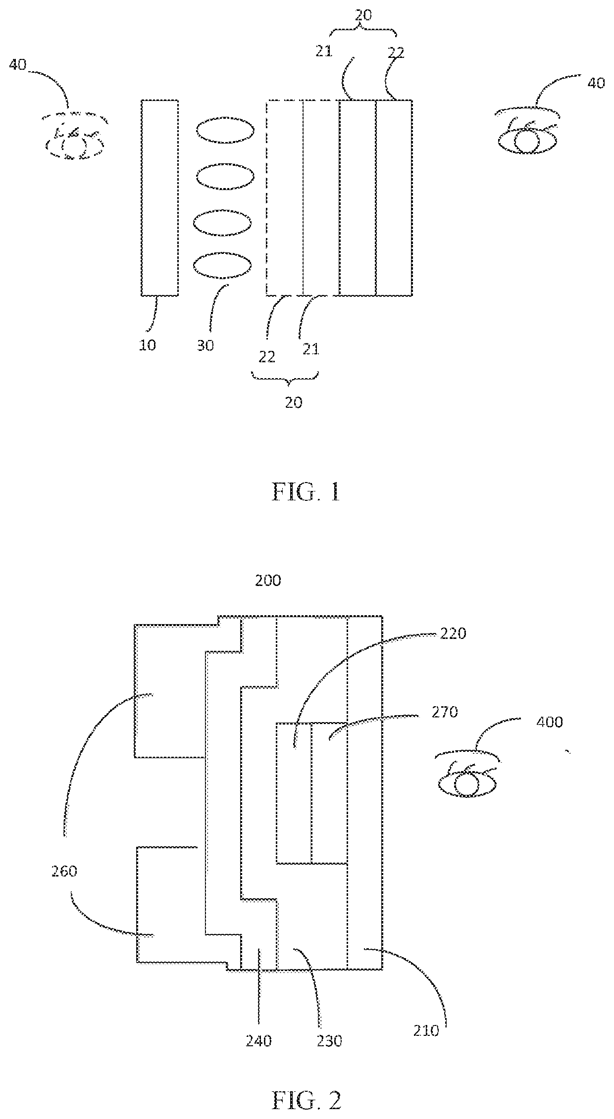
[0048]Please refer to FIG. 1, which is a schematic structural diagram of a display panel according to the present application. The display panel includes:

[0049]a color filter substrate 10, an array substrate 20 disposed correspondingly to the color filter substrate 10 and including two metal layers 21; and a liquid crystal layer 30 sandwiched between the color filter substrate 10 and the array substrate 20, wherein a reflection blocking layer 22 is disposed on one of the metal layers 21 near a viewer 40, to reduce a reflectance of the array substrate 20 to ambient light.

[0050]In this embodiment, the metal layers that strongly reflect ambient light are covered with the reflection blocking layer 22, which can effectively reduce a reflection of the metal layers 21 to ambient light in a viewing angle of a viewer, thereby improving display contrast, thus beneficial to improving a viewing experience of the viewer 40.

[0051]Specifically, in the display panel, a side of the color filter subs...

second embodiment

[0052]In an embodiment, please refer to FIG. 2. FIG. 2 is a schematic structural diagram of a display panel according to the present application. In the case that the array substrate 200 faces the viewer 400, the array substrate 200 includes a support substrate 210; and a first metal layer 220, a first insulating layer 230, an active layer 240, and a second metal layer 260 sequentially disposed on the support substrate 210, wherein the reflection blocking layer 270 is disposed between the support substrate 210 and the first metal layer 220.

[0053]In this embodiment, the first metal layer 220 may be a gate layer; and the second metal layer 260 is a source / drain layer. The active layer may be a polysilicon layer, and the first insulating layer 230 may be made of an organic material or an inorganic material. When the insulating material is an inorganic material, it may be silicon nitride, silicon oxide, or a composite thereof. When the insulating material is made of an organic material,...

fourth embodiment

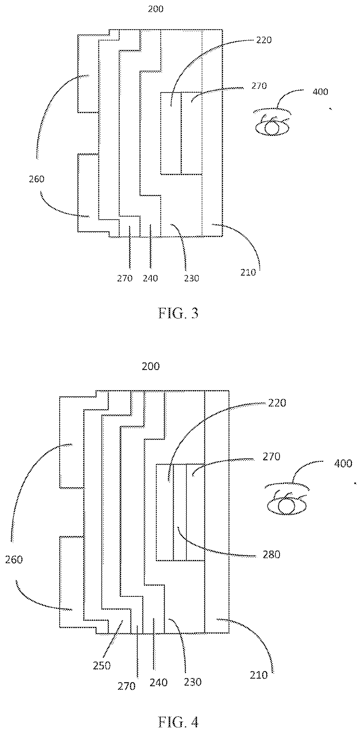
[0056]Further, please refer to FIG. 4, which is a schematic structural diagram of a display panel according to the present application. The display panel further includes a first intermediate layer 280 disposed between the reflection blocking layer 270 and the first metal layer 220 to improve an adhesion between the reflection blocking layer 270 and the first metal layer 220. Specifically, the first intermediate layer 280 may be made of silicon nitride and / or silicon oxide. Further, the display panel further includes a second intermediate layer 250 disposed between the reflection blocking layer 270 and the second metal layer 260 to improve the adhesion between the reflection blocking layer 270 and the second metal layer 260. Specifically, the second intermediate layer 250 may be made of silicon nitride and / or silicon oxide.


PUM

PropertyMeasurementUnit
Adhesion strengthaaaaaaaaaa
Reflectionaaaaaaaaaa
Reflectanceaaaaaaaaaa

Abstract

The present invention discloses a display panel, a manufacturing method, and a display device, wherein the display panel includes: a color filter substrate; an array substrate disposed correspondingly to the color filter substrate and comprising two metal layers; and a liquid crystal layer sandwiched between the color filter substrate and the array substrate, wherein a reflection blocking layer is disposed on one of the metal layers near a viewer, to reduce a reflectance of the array substrate to ambient light. The present invention can improve display contrast, thus beneficial to improving a viewing experience of the viewer.

Description

BACKGROUND OF INVENTIONField of Invention[0001]The present invention relates to the field of display technology, and in particular, to a display panel, a manufacturing method and a display device.Description of Prior Art[0002]Contrast is one of important indicators to evaluate image quality performance of a liquid crystal display (LCD). In a real use scene, due to the influence of the surrounding ambient light, a reflectivity of the display panel will affect the contrast of the screen. As shown in the formula below, Lon, Loff, and Rambient respectively indicate a bright state of the display panel, a dark state brightness of the display panel, and an ambient brightness, and RL represents a reflectivity of the display panel. One can increase the contrast of the display panel by two aspects: 1) increasing the bright state brightness Lon of the display panel, and 2) reducing the reflectivity RL of the display panel.Contrast=(Lon+Lambient*RL) / (Loff+Lambient*RL)[0003]In the prior art, met...

Claims


Application Information

Patent Timeline
IPC IPC(8): G02F1/1362G02F1/1368C09B3/14C09B67/20C08K5/3437C08K3/04C08K13/02G03F7/09
CPCG02F1/136209G02F1/1368C09B3/14C09B67/0063G02F2202/04C08K3/04C08K13/02G03F7/091C08K5/3437G02F1/133512G02F1/133514G02F1/13737G03F7/004G03F7/105G03F7/0007C08K5/0041C09B67/0033C09K2323/031
Inventor YU, XIAOPING
Owner TCL CHINA STAR OPTOELECTRONICS TECH CO LTD
Why Eureka
Try Eureka