

Phase Difference Compensator, Light Modurating System, Liquid Crystal Display and Liquid Crystal Projector
- Summary
- Abstract
- Description
- Claims
- Application Information
AI Technical Summary
Benefits of technology
Problems solved by technology
Method used
Image

Examples
first embodiment
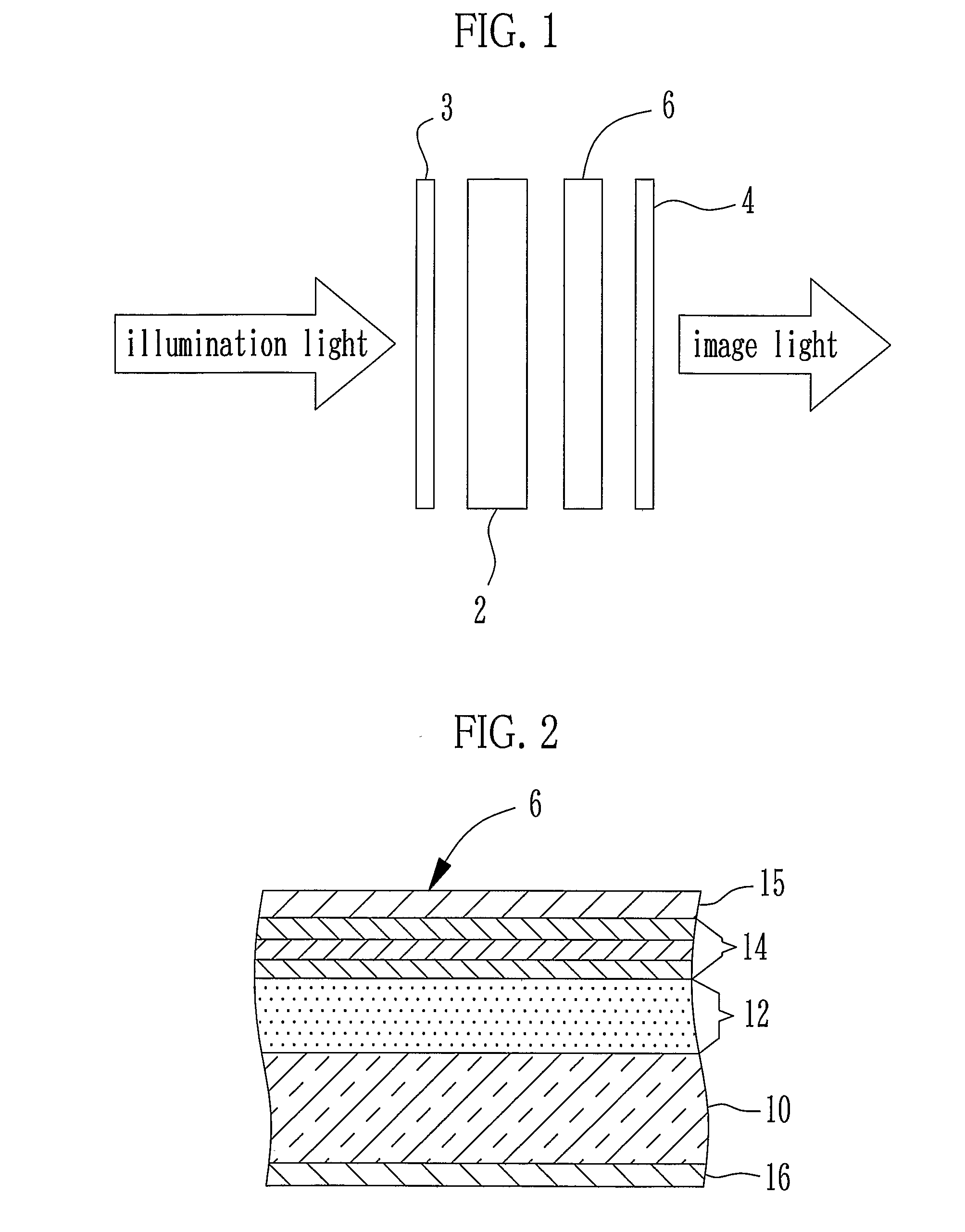
[0063] A phase difference compensator of the present invention is now described. A liquid crystal display with use of the phase difference compensator has a conceptual structure as shown in FIG. 1. Polarizing plates 3, 4 are respectively disposed at a light incident surface side and a light exit surface side of a TN liquid crystal element 2. The polarization axes of the polarizing plates 3 and 4 used in a normally white mode are perpendicular to each other (cross nicol configuration). The polarizing plate 3 is a polarizer which converts illumination light into linearly polarized light. The polarizing plate 4 is an analyzer which transmits a part of the light modulated by the TN liquid crystal element 2, whose polarization direction corresponds to that of the polarizing plate 4, and shields a remaining light from the TN liquid crystal element 2.
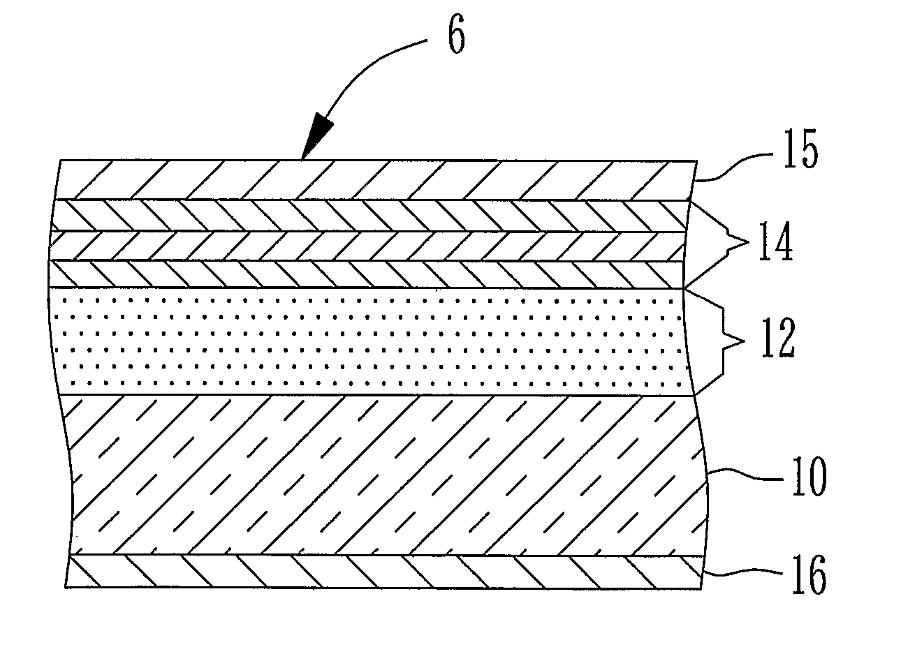
[0064] Between the TN liquid crystal element 2 and the polarizing plate 4, the phase difference compensator 6 of the first embodiment of the ...
experiment 1
[0093] (Experiment 1)
[0094] Corning 1737 (50 mm×50 mm) as the glass substrate was washed by acetone and sufficiently dried, and then set in a deposition device for performing normal front deposition (β=0°). A vacuum chamber discharged the air to be 1×10⁻⁴ Pa, and the glass substrate was heated at 300° C. to form a three-layer anti-reflection film. The anti-reflection film was a stacked SiO2 of λ / 4 optical thickness, TiO2 of λ / 2 optical thickness, and SiO2 of λ / 4 optical thickness in this order from the side of the glass substrate. The reference wavelength λ was 550 nm.
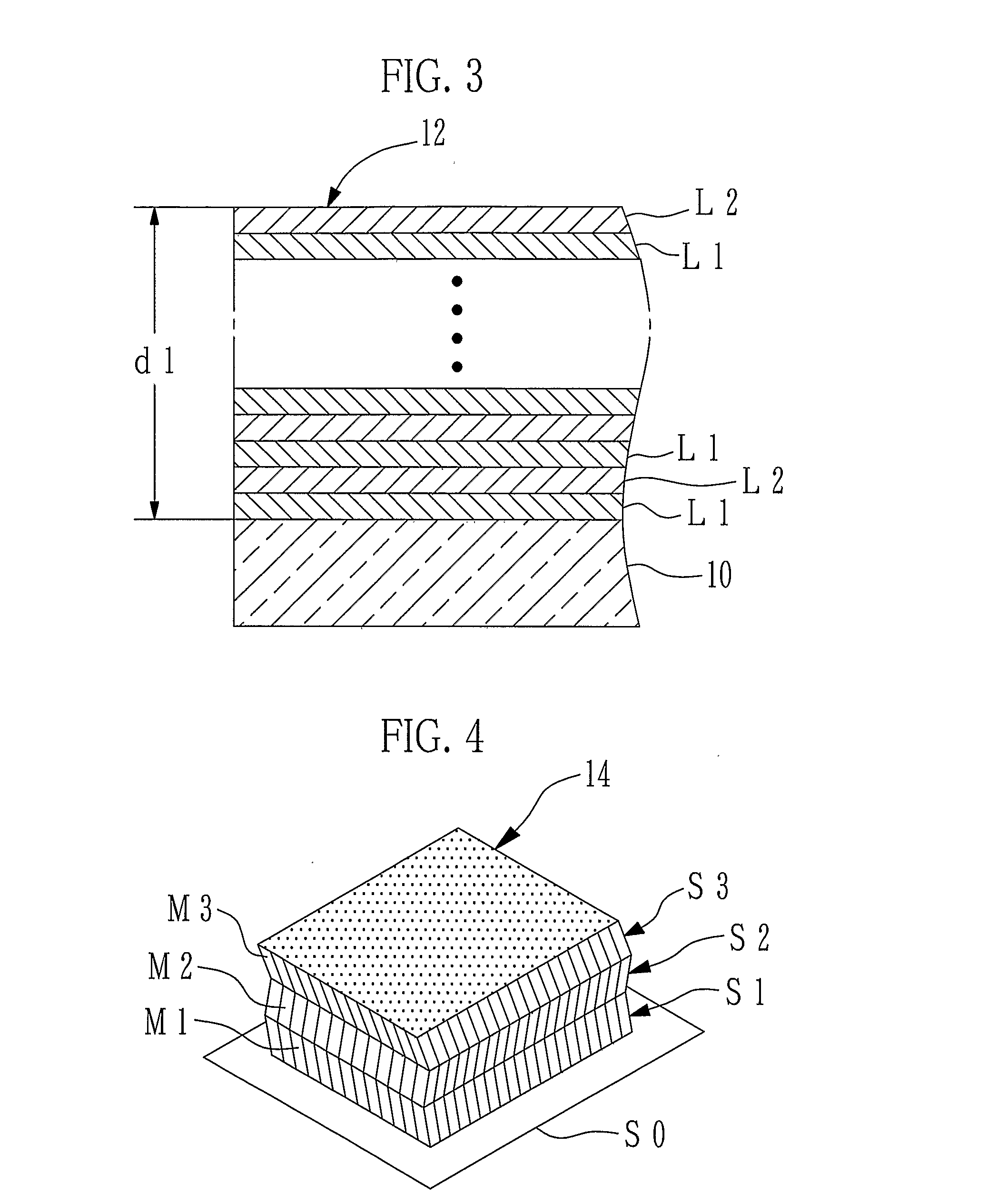
[0095] After forming the anti-reflection layer, the glass substrate was turned inside out in the vacuum chamber, to form the first phase difference compensating layer. The first phase difference compensating layer comprised multilayer film in which two kinds of deposition films L1, L2 were alternately stacked as shown in FIG. 3. The retardation (dΔn) thereof was negative. Since the retardation (dΔn) can be controlled ...
experiment 2
[0101] (Experiment 2)
[0102] As same as Experiment 1, a sample of Experiment 2 was formed. The constructions of the TN liquid crystal element and the anti-reflection layer were same as Experiment 1, and the film constructions of the first and second phase difference compensating layers were different from Experiment 1. Constructions and parameters of the first and second phase difference compensating layers are shown in Table 2. In Experiment 2, the second phase difference compensating layer has three films, and the azimuth α of each film is rotated in a same direction. Accordingly, the optical axis vectors P1 to P3 are rotated sequentially in counterclockwise direction in a spiral manner on the deposition surface.
TABLE 2azimuthpolar(dΔn)Experiment 2α°angle β°(nm)second phaseS3−154470differenceS2−412780compensatingS1−12745190layerfirst phase−370differencecompensatinglayerglasssubstrate
[0103] The contrast ratio curve of Experiment 2 is shown in FIG. 12. A high contract region became...
PUM
 Abstract
Description
Claims
Application Information