Wireless intra oral sensor holder

a sensor and wireless technology, applied in the field of intraoral xray imaging sensors, can solve the problems of causing pain, sheer pain, pain and discomfort, and the bracket is holding up, so as to reduce the signal, increase the inactive area, and “wasting” useful radiation

Active Publication Date: 2021-09-23
ATHLOS OY
View PDF0 Cites 5 Cited by
  • Summary
  • Abstract
  • Description
  • Claims
  • Application Information

AI Technical Summary

Benefits of technology

[0019]Furthermore, the wired sensor discomfort is compounded by sensor holder designs that, due to the cable on the backside, grab the sensor from the sides. This, as mentioned already, creates pain when the brackets come into contact with human tissue. In many cases the brackets holding the sensor from its edges introduce a plastic or other type of layer on the front of the sensor, i.e., the direction of incidence of the x-rays, reducing the signal and “wasting” useful radiation. Finally bracket solutions holding the sensor from the sides (long or short edges), increase the inactive area. This means that in order to image the mandibular or maxillary posterior teeth additional pressure is applied to push the sensor towards the roots of the teeth with the holder brackets making contact with the tissue. Again, more pain and discomfort is caused because of this.
[0020]It has been observed that it would be extremely desirable and a major advancement in the field of intraoral x-ray imaging to be able to provide a completely wireless intraoral sensor, i.e. an intraoral sensor without a cable coming off the back of the sensor that is inserted to the human mouth and to match this with an innovative holder design that mitigates the pain and discomfort caused by prior art holders. To that effect embodiments of the present invention provide a wireless intraoral x-ray imaging sensor holder which holds the sensor in place by locking, clipping or generally attaching to the sensor from the battery-hump on the backside (opposite face) of the sensor's active area, without any brackets grabbing the sensor from its short or long edges (sidewalls). The holder attaches to and holds the sensor from the hump whereas the hump is the part of the encapsulation covering the rechargeable compact battery suitably positioned with an adequate distance from the edge of the Printed Circuit Board (PCB) (or ceramic). This allows the encapsulation of the battery on the backside to not be in contact with the edges of the sensor thus providing a comfortable and easy way to position the sensor inside the mouth once the sensor is attached to the holder. Because the holder is attached to the battery-hump, the edges (sidewalls) of the sensor are free of any brackets and the sensor feels comfortable and pain free, even when coming to contact with the human tissue.

Problems solved by technology

The holding bracket is causing discomfort and in many cases sheer pain as it is then pushed against the mandibular, maxillary or anterior tissue.
It has been observed that current intraoral sensor holders made for intraoral sensors with a cable (wire) suffer from one or more of the following deficiencies:a) They cause pain and discomfort, because in most case the sensor is held with brackets around the edges and these brackets come into contact with the sensitive human tissue;b) They introduce a layer of material on the path of the incoming x-rays, i.e. valuable x-ray signal is lost;c) They increase the inactive area
The presence of the cable coming out of the mouth is creating discomfort to the patients and makes positioning of the sensor difficult.
In many cases the discomfort and the difficulty in positioning leads to faulty exposures and as a result a new exposure is required.
Additionally, the cable and in particular the area where the cable comes out from the back of the sensor is one of the main failure points of the sensor.
Quite often the cable close to or at the backside contact will break.
As a result, the connection needs to be reinforced causing a relatively large hump on the back of the sensor in all three dimensions.
This large hump causes more inconvenience to the patient.
It has been observed that a viable wireless intraoral sensor may fail for mainly the following reasons:The wireless sensor is powered by a single use battery that will last a few exposures and will have to be disposed afterwards.
A new battery will have to be used subsequentlyA wireless link is not reliable and data is lost all too often, creating the need of additional exposureThe sensors, although wireless, are bulky mainly due to the use of indirect conversion scintillator with a thick fiber optic plate, single use thick battery packs and bulky wireless electronicsThe sensors are fragile and sensitive.
Furthermore, the wired sensor discomfort is compounded by sensor holder designs that, due to the cable on the backside, grab the sensor from the sides.
This, as mentioned already, creates pain when the brackets come into contact with human tissue.
Again, more pain and discomfort is caused because of this.

Method used


Image

  • Wireless intra oral sensor holder
  • Wireless intra oral sensor holder
  • Wireless intra oral sensor holder

Examples


Embodiment Construction

[0055]With reference now to the accompanying figures we describe in detail the invention and the preferred embodiments.

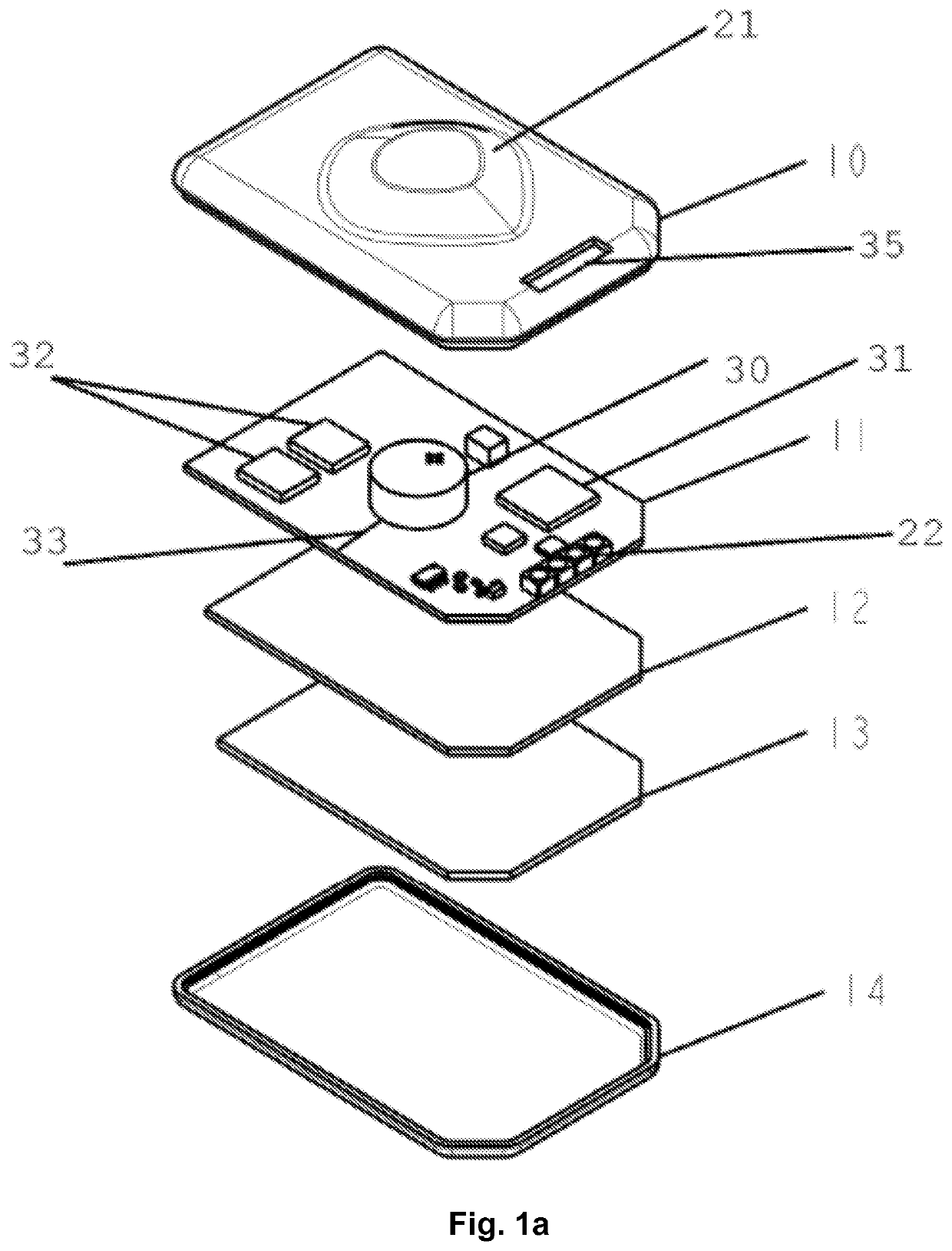
[0056]With reference now to FIG. 1a, a direct conversion wireless intraoral sensor comprises a Silicon (Si) direct conversion semiconductor detector substrate 13 bonded to a readout substrate 12 which is an Application Specific Integrated Circuit (ASIC). Typically such readout ASIC substrates comprise Complementary Metal Oxide Semiconductor (CMOS). The Si-CMOS hybrid has an active area sensitive to incoming x-rays. In dental intraoral x-ray imaging there are worldwide three different active area sensors, independently to what is the detector material or detection technique. The three different intraoral sensor categories are: a) size 0 with active area 15-18 mm×20-24 mm, b) size 1 with active area 19-23 mm×28-32 mm and c) size 2 with active area 24-27 mm×33-36 mm.

[0057]With reference to FIG. 1a, we depict a size 2 wireless intraoral x-ray imaging sensor. The Si-CMOS...


PUM


Abstract

Disclosed is an intraoral dental x-ray imaging sensor holder for Wireless IntraOral x-ray imaging Sensors (“WIOS”). The holder secures in place the WIOS from the hump on the backside of the WIOS corresponding to the battery. The holder with the WIOS attached can be painlessly and comfortably positioned inside the dental arch, since there are no brackets holding the WIOS from its edges, but instead from the battery hump. Additionally, the WIOS can be secured on the holder in reverse (rotated by 180 degrees) thus adding flexibility and versatility during intraoral x-ray imaging.

Description

FIELD OF THE INVENTION[0001]The present invention relates to intraoral x-ray imaging sensors and more specifically to wireless intraoral imaging sensors (WIOS).BACKGROUND OF THE INVENTION[0002]Intraoral imaging utilizing sensors has the advantage of immediate (less than 10 seconds) display on the computer screen of the diagnostic intraoral images as opposed to the use of phosphor plates which require a reader for extracting the digital image. Additionally, several images can be taken one after the other to create a full mouth series or a bite wing series. An intraoral x-ray imaging sensor has typically a detector to convert incoming x-rays to either visible light (indirect conversion) or to electric pulse (direct conversion). Examples of indirect conversion intraoral detector include cesium iodide (CsI) deposited on a fiber optic plate. Examples of direct conversion intraoral detectors include silicon (Si), cadmium telluride (CdTe) and mercuric iodide (HgI2), although none of the di...

Claims


Application Information

Patent Timeline
Patent Type & Authority Applications(United States)
IPC IPC(8): A61B6/14H04N5/32G03B42/04
CPCA61B6/145A61B2560/0214H04N5/32G03B42/042A61B6/563A61B6/4429
Inventor SPARTIOTIS, KONSTANTINOSGENNADIOS, GEORGEGRAMMATIKAKIS, VASILEIOS
Owner ATHLOS OY
Why Eureka
Try Eureka