
Laser interference device

Active Publication Date: 2021-09-23
MITUTOYO CORP
View PDF0 Cites 0 Cited by
  • Summary
  • Abstract
  • Description
  • Claims
  • Application Information

AI Technical Summary

Benefits of technology

The invention is a laser interference device that does not require complicated calibration. It uses a method to accurately measure the displacement of a movable mirror through the measurement of wavelength changes in the laser beam. By periodically updating the wavelength measurement value and storing it in an accumulative manner, the device can monitor changes in the laser beam with time. Additionally, the distance between the measurement laser or reference laser and the light detector can be adjusted to reduce the influence of heat emitted from the lasers on an optical path length difference between the measurement light and reference light. This improves the accuracy of the device's displacement measurement.

Problems solved by technology

However, a typical calibration work, which includes a work of removing the laser from the laser interference device and setting the laser in a wavelength measurement device and a work of restoring the removed laser in the laser interference device, is a complicated work accompanied with optical adjustment.

Method used


Image

  • Laser interference device
  • Laser interference device
  • Laser interference device

Examples


Embodiment Construction

)

[0024]Description will be made on an exemplary embodiment of the invention with reference to the attached drawings.

Laser Interference Device

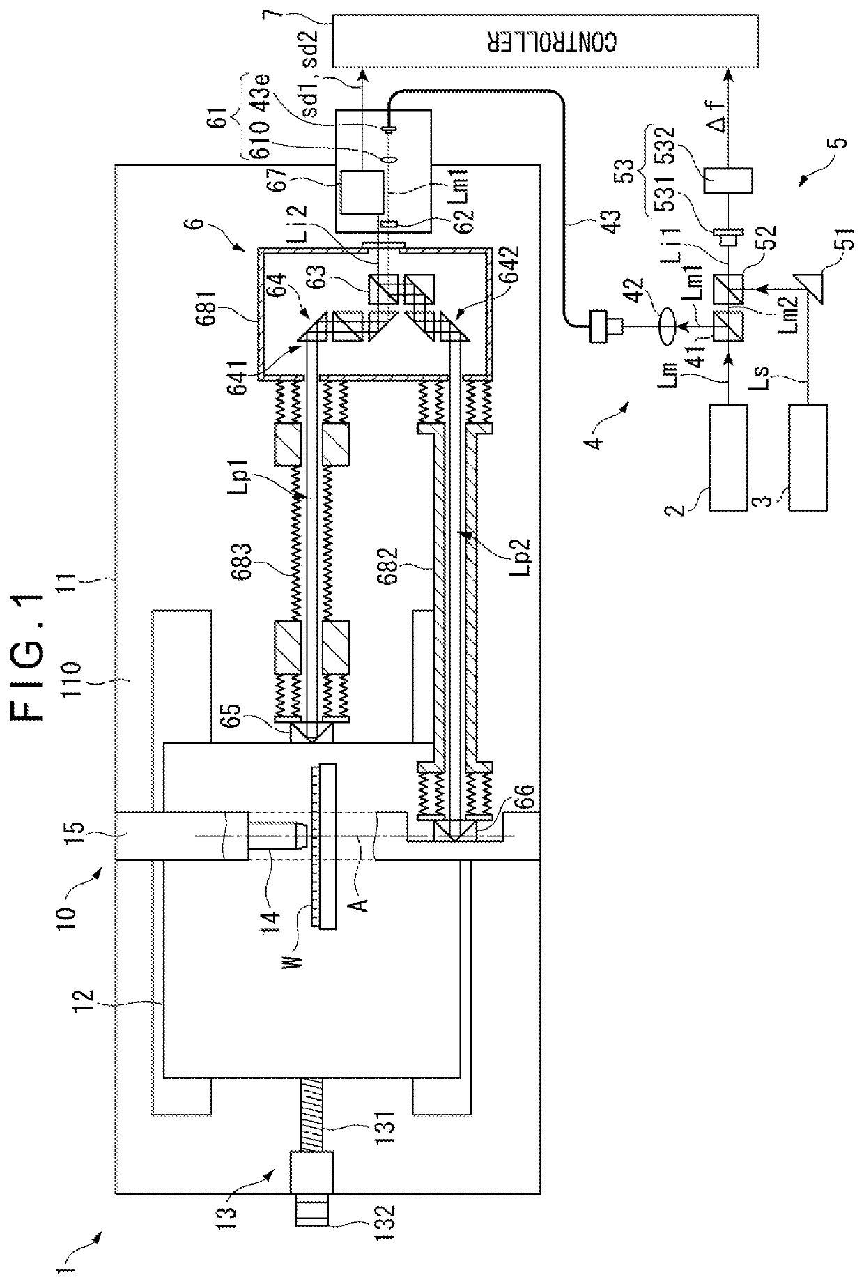
[0025]As shown in FIG. 1, a laser interference device 1 of the exemplary embodiment is provided as a device configured to measure a unidirectional displacement of a slider 12 on which an object W is placed.

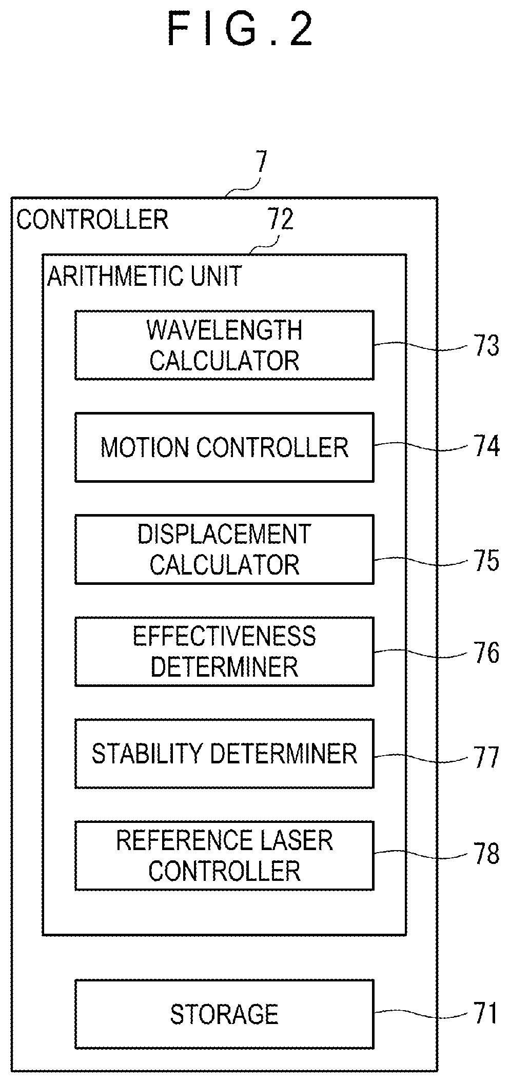
[0026]The laser interference device 1 includes: a measurement laser 2 configured to output a laser beam Lm; a reference laser 3 configured to output a reference laser beam Ls; a light guide 4 configured to divide the laser beam Lm into a measurement laser beam Lm1 and a frequency monitor laser beam Lm2 and guide the measurement laser beam Lm1 and the frequency monitor laser beam Lm2; a first interferometer 5 for measuring a wavelength of the frequency monitor laser beam Lm2; a device body 10 (including a second interferometer 6) for measuring a displacement of the slider 12; and a controller 7.

[0027]The measurement laser 2, which is, for inst...


PUM


Abstract

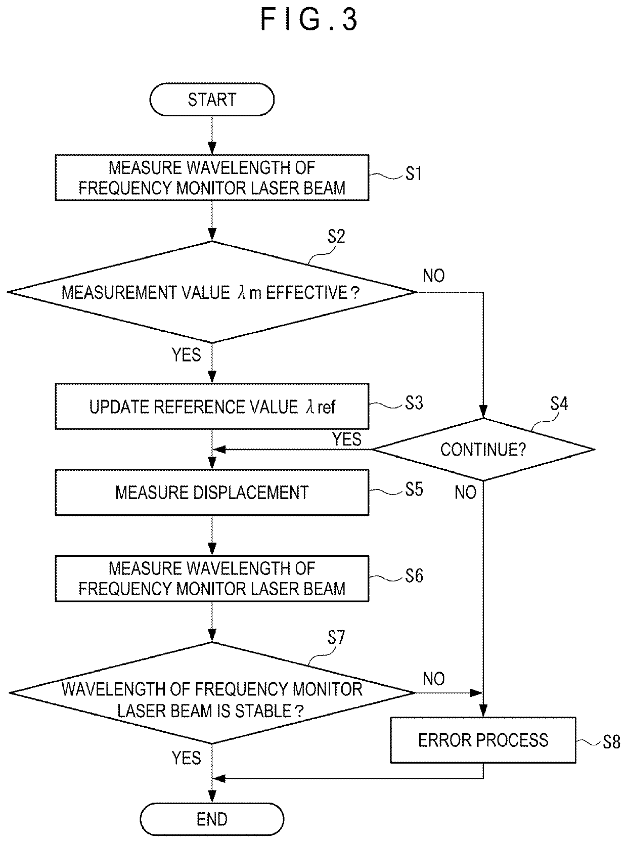
A laser interference device includes a measurement laser that outputs a laser beam, a beam splitter that divides the laser beam into a measurement laser beam and a frequency monitor laser beam, a reference laser that outputs a reference laser beam, a frequency detector that detects a beat frequency resulting from interference between the reference laser beam and the frequency monitor laser beam, a wavelength calculator that calculates a wavelength of the frequency monitor laser beam (a wavelength measurement value) on the basis of the beat frequency, a light detector that detects an interference light of the measurement light and the reference light of the measurement laser beam and outputs a light detection signal, and a displacement calculator that calculates a displacement of the measurement mirror by performing an arithmetic process based on the wavelength measurement value and the light detection signal.

Description

[0001]The entire disclosure of Japanese Patent Application No. 2020-049329 filed Mar. 19, 2020 is expressly incorporated by reference herein.TECHNICAL FIELD[0002]The present invention relates to a laser interference device.BACKGROUND ART[0003]In a measuring instrument, an ultraprecision machining device, or the like, a Michelson laser interference device has been used as means for measuring a displacement of a movable body with a high accuracy (for instance, see Patent Literature 1: JP 3400393 B).[0004]In such a laser interference device, a laser beam outputted from a laser is divided into a measurement light and a reference light by a beam splitter. The measurement light is reflected by a movable mirror attached to the movable body, while the reference light is reflected by a reference mirror disposed at a predetermined position. The reflected lights are superimposed on each other, generating an interference light. Assuming that λ denotes a wavelength of the laser beam, interferenc...

Claims


Application Information

Patent Timeline
IPC IPC(8): G01B9/02G02B27/10
CPCG01B9/02003G01B9/02027G01B2290/60G01B2290/70G01B2290/45G02B27/1006G01B9/02072
Inventor YOKOYAMA, YUICHIRO
Owner MITUTOYO CORP
Learn More