Robot joint member, dynamic joint and robot with heat dissipation structure

a robot and heat dissipation structure technology, applied in the field of robots, can solve the problems of low heat dissipation efficiency, large volume of dynamic joints, and inability to meet the needs of dynamic joints with large torques, and achieve high heat dissipation efficiency, good heat conduction effect, and quick elimination of heat accumulation of joint power sources

Active Publication Date: 2021-11-04
BEIJING INSTITUTE OF TECHNOLOGYGY
View PDF2 Cites 2 Cited by
  • Summary
  • Abstract
  • Description
  • Claims
  • Application Information

AI Technical Summary

Benefits of technology

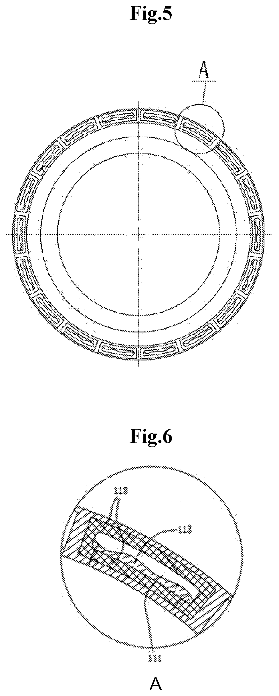
[0010]heat dissipation auxiliary ribs are arranged on a periphery of the barrel wall of the joint member and a side of the phase change heat dissipation unit away from the heat source component; and the heat dissipation auxiliary ribs define a plurality of gas flow channels with cross sections gradually reduced along a gas flow direction, so that gas flows are accelerated in the gas flow channels. The present disclosure disposes variable-area heat dissipation auxiliary ribs for a gas flow adjustment on a low-temperature side of the phase change heat dissipation units, so that the gas flow speed and the heat exchange efficiency are improved under the double effects of the Bernoulli principle and the negative pressure of the hot gas flow.
[0020]According to the joint member with the heat dissipation structure in the embodiments of the present disclosure, the phase change heat dissipation units are disposed along the barrel wall outside the heat source component, the heat generated by the heat source component is absorbed by the phase change working mediums inside the phase change heat dissipation units, and a phase change is produced to realize the heat release of the heat source component, which has a good heat conduction effect and a high heat dissipation efficiency. The heat accumulation of the joint power source can be quickly eliminated by the phase change circular heat dissipation. In addition, the phase change heat dissipation units are located on the joint member, so that the additional use of a liquid cooling pipeline is avoided, and the dynamic joint of the robot can keep a compact structure. In addition, the heat dissipation auxiliary ribs are disposed outside the joint member to form a plurality of variable-area gas flow channels, thereby further improving the gas flow speed and the heat exchange efficiency.

Problems solved by technology

In this way, the heat dissipation efficiency is low, which only meets the needs of general application working conditions with low requirements but is not suitable for dynamic joints with large torques.
Although this liquid cooling method has a better heat dissipation efficiency relative to the joint without a heat dissipation structure, it often requires a large external heat dissipation circulation device, so the dynamic joint has a large volume and the mounting is inconvenient.
Neither the existing method that dissipates heat by a heat conduction of a joint member itself, nor the liquid cooling method meets the increasingly demand on larger output load and smaller volume of the joint unit of the robot.
That is, although the existing heat dissipation method of the dynamic joint can meet the general heat dissipation performance requirements, it cannot deal with the working conditions expected by customers, such as continuous large torque output or high exploration overload, or there are problems such as too large external liquid cooling auxiliary device and slow influence, which cannot meet the requirements of larger output load and compact structure and size of the dynamic joint of the robot.
With the continuous improvement requirements of persistent large torque, high explosive force and high overload capacity of various robots, the loads of the dynamic joint and the motors are increasingly larger, which leads to the problem of heat accumulation in the motor.
With the continuous output of the motor, if the accumulated heat cannot be effectively dissipated, the stability of the motor and the dynamic joint will be affected.
Therefore, the heat dissipation problem of the motor has become an obstacle to the increasing power of the robot dynamic joint and has been increasingly severe, so it is increasingly urgent to solve the core heat dissipation problem of the dynamic joint.

Method used


Image

  • Robot joint member, dynamic joint and robot with heat dissipation structure
  • Robot joint member, dynamic joint and robot with heat dissipation structure
  • Robot joint member, dynamic joint and robot with heat dissipation structure

Examples


Embodiment Construction

[0036]In order that the objectives, technical solutions and advantages of the embodiments of the present disclosure are clearer, the embodiments of the present disclosure will be further described in detail as follows with reference to the drawings. Here, the illustrative embodiments and the descriptions thereof are used to explain the present disclosure, rather than limitations to the present disclosure. In the drawings of the present disclosure, the same reference numerals refer to the same or similar components.

[0037]Here, it should be noted that in order to avoid obscuring the present disclosure due to unnecessary details, only the structures and / or processing steps closely related to the solutions of the present disclosure are illustrated in the drawings, and other details not very related to the present disclosure are omitted.

[0038]It should be emphasized that the term ‘include / comprise / have’ as used herein refers to the presence of features, elements, steps or components, but...


PUM


Abstract

The present disclosure provides a robot joint member, a dynamic joint and a robot with a heat dissipation structure. The joint member has a hollow barrel structure disposed to sleeve a heat source component, and a plurality of phase change heat dissipation units; the phase change heat dissipation unit comprises a phase change working medium, a capillary material and a sealed phase change cavity; heat dissipation auxiliary ribs are arranged on a periphery of the barrel wall of the joint member and a side of the phase change heat dissipation unit away from the heat source component; and the heat dissipation auxiliary ribs define a plurality of gas flow channels with cross sections gradually reduced along a gas flow direction. The joint member has can quickly eliminate the heat accumulation of the joint power source, and can keep a compact structure of the dynamic joint of the robot.

Description

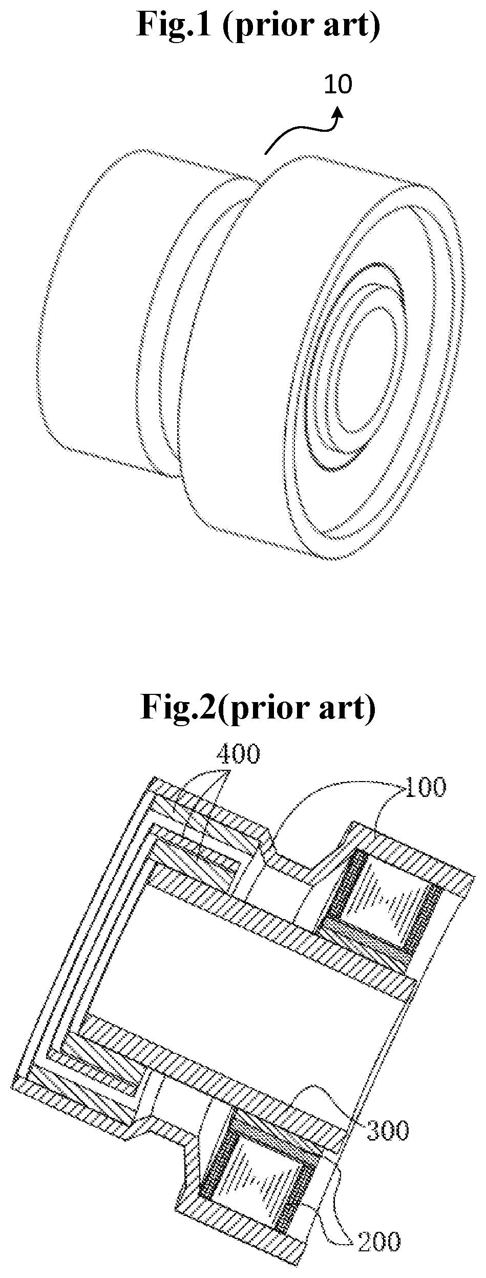
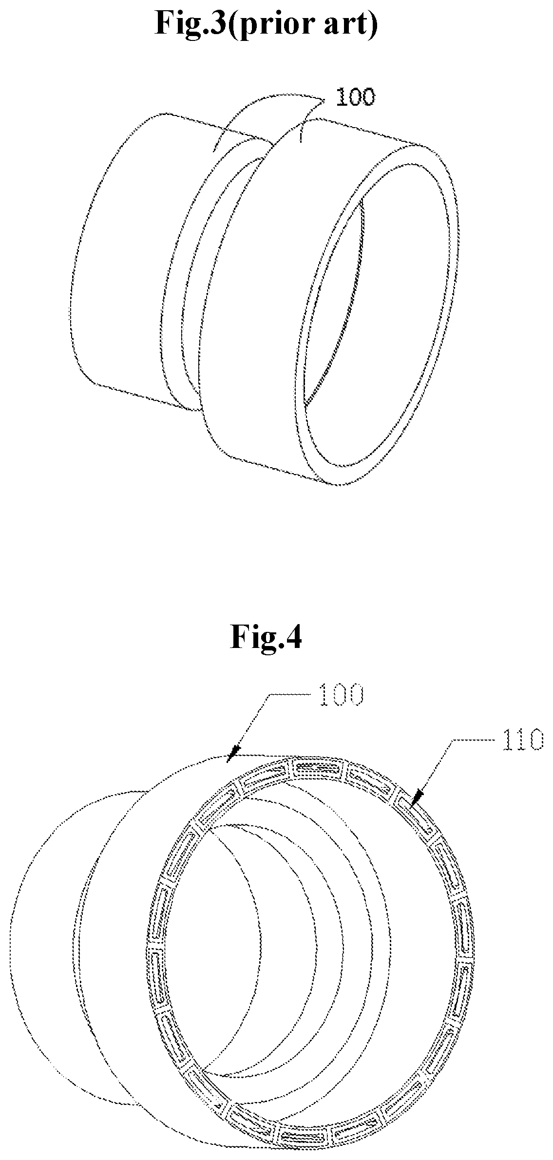
[0001]This application claims priority to Chinese Patent Application No. CN202010366106.9, filed on Apr. 30, 2020, which is hereby incorporated by reference in its entirety as if fully set forth herein.TECHNICAL FIELD[0002]The present disclosure relates to the field of robot technologies, and particularly, to a robot joint member, a dynamic joint and a robot with a heat dissipation structure.BACKGROUND ART[0003]As illustrated in FIGS. 1, 2 and 3, a dynamic joint 10 of a robot generally includes a motor 200, a reducer 400 and a joint member 100; the motor 200 and the reducer 400 are mounted in the hollow joint member 100, the motor 200 is energized to rotate to provide a power source to the dynamic joint, the motor 200 and the reducer 400 are connected through a transmission shaft 300 for transmission, a rotary speed output via the motor is reduced by the reducer 400 to increase an output torque, and the joint member 100 provides support, heat dissipation, mounting configuration and ...

Claims


Application Information

Patent Timeline
Patent Type & Authority Applications(United States)
IPC IPC(8): B25J19/00B25J17/00B25J9/10
CPCB25J19/0054B25J9/102B25J17/00
Inventor HUANG, QIANGZHANG, WUQIU, DONGLINYU, ZHANGGUOLIU, XINGZHONG
Owner BEIJING INSTITUTE OF TECHNOLOGYGY
Why Eureka
Try Eureka