Portable power tool comprising an epicyclic reduction gear

a technology of epicyclic reduction and power tools, which is applied in the field of portable power tools, can solve the problems of axial and radial maintenance of ball screws, space occupation, and the inability to meet the requirements of a portable tool, and achieve the effect of preserving the compactness of tools and contributing to the compactness of transmission

Inactive Publication Date: 2018-07-12
PELLENC SA
View PDF5 Cites 0 Cited by
  • Summary
  • Abstract
  • Description
  • Claims
  • Application Information

AI Technical Summary

Benefits of technology

[0039]In other words, the end of the ball screw may be free which increases the length of the ball screw available for the travel of the ball nut, while conserving the compactness of the tool.
[0040]The concentric character of the stabilization bearing inside the axial boring of the output shaft of the reduction gear is likewise a characteristic which contributes to the compactness of the transmission.

Problems solved by technology

One of the difficulties encountered with transmissions of this type is the axial and radial maintenance of the ball screw.
These loads tend to bend the ball screw relative to its axis.
It also poses problems of space taken up, of cost and weight for a portable tool.
Furthermore, the radial constraints of the ball screw are not necessarily contained in a satisfactory manner.
This solution ensures good stability of the ball screw but may pose alignment problems of the bearings.
It also poses problems with respect to space requirements and limitation of the track of the ball nut at the end of the ball screw.
Finally, it requires a more complex design of the cutting blade, and in particular of its cam, resulting in a heavier weight.
Such a solution remains subject to limits in terms of cost, space requirements and weight.
In any case, this solution involves also a very significant take-up of the radial loads by the reduction gear.

Method used


Image

  • Portable power tool comprising an epicyclic reduction gear
  • Portable power tool comprising an epicyclic reduction gear
  • Portable power tool comprising an epicyclic reduction gear

Examples


Embodiment Construction

[0068]In the following description all identical or similar portions of the various figures are identified by the same reference signs. It is thus possible to refer from one figure to another. The figures are shown in free scale.

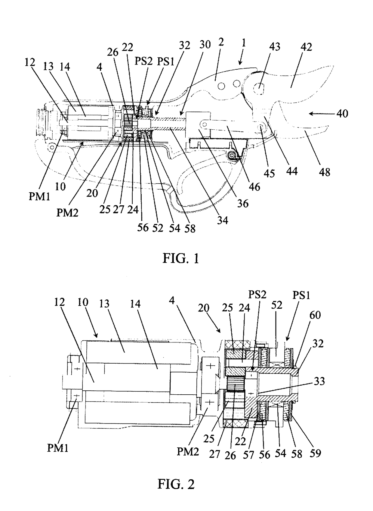
[0069]FIG. 1 represents in cross-section an electric pruning shear 1. The electric pruning shear 1 comprises a main housing 2 accommodating an electric motor 10, an epicyclic reduction gear 20 mounted on a drive shaft 12 of the motor, and a ball nut-screw mechanism 30.

[0070]The shaft 12 of the electric motor 10 is kept in the housing by two motor bearings PM1 and PM2 located on either side of the motor 10. The bearings PM1 and PM2 preferably consist of ball bearings.

[0071]In the example shown, the motor 10 includes a stator 13 and a rotor 14. The presence of an intermediate housing 4 receiving the motor 10 and the epicyclic reduction gear 20 can also be noted. The intermediate housing 4 is received in the main housing 2 of the electric pruning shear.

[0072]Th...


PUM

PropertyMeasurementUnit
diameteraaaaaaaaaa
pitch diameteraaaaaaaaaa
rotary speedaaaaaaaaaa

Abstract

A portable power tool including, within a housing: an electric motor having a drive shaft, an epicyclic reduction gear having planetary gears meshing with a central gear of the drive shaft of the electric motor, the reduction gear being provided with an output shaft that is rigidly connected to a ball screw of a ball screw/nut mechanism and is coaxial to the ball screw, and a support bearing connecting the output shaft to the housing. The tool includes at least one stabilization bearing axially offset relative to the support bearing. The stabilization bearing connects the output shaft of the epicyclic reduction gear to the housing by at least one intermediate part selected from: the drive shaft of the electric motor, planet-carrier axles of the epicyclic reduction gear, and epicyclic reduction gears of the epicyclic reduction gear. The structure is of use in shears, in particular sheet metal shears.

Description

TECHNICAL FIELD[0001]The present invention concerns a portable power tool and more precisely, such a tool utilizing a transmission to transform the rotary motion of an electric motor into a longitudinal movement of translation of an active element such as, for example, a transmission comprising a mechanism of the ball screw-nut type.[0002]The invention finds general applications in the production of transmission mechanisms and in the manufacture of portable power tools using a mechanism transforming a rotary movement of a motor into a longitudinal movement of translation such as, for example, the one provided by a ball screw-nut mechanism. The invention finds applications particularly in the manufacture of pruning shears or sheet metal shears.State of Prior Art[0003]Portable power tools such as pruning shears and sheet metal shears generally feature a housing forming a handle. The housing serves as support for a cutting element and accommodates an electric motor for activating the c...

Claims


Application Information

Patent Timeline
Patent Type & Authority Applications(United States)
IPC IPC(8): B25F5/00B23D29/00A01G3/037
CPCB25F5/001B23D29/005A01G3/037B25B1/10B23D17/04F16H2025/2087
Inventor PELLENC, ROGER
Owner PELLENC SA
Why Eureka
Try Eureka