
Sensor arrangement and optimized tracking for csp systems

Pending Publication Date: 2021-11-04
CAMBRAS GMBH
View PDF0 Cites 0 Cited by
  • Summary
  • Abstract
  • Description
  • Claims
  • Application Information

AI Technical Summary

Benefits of technology

The present invention aims to provide a better CSP system that is easy to use, economical, durable, and accurate. Additionally, it should improve the tracking and operation of solar fields that have multiple CSP systems.

Problems solved by technology

Still, existing systems suffer from suboptimal tracking due to tolerances, e.g., with in the overall construction of the parabolic trough as well as within the power train of the tracking system as well as due to suboptimal tracking algorithms and / or tracking sensor arrangements.
However, this entails problems in practice.
Furthermore, deviations from the pre-calculated or calculable radiation paths occur due to constructional inaccuracy during building the system, constructional inaccuracy developing in the course of operation, e.g., base movements, as well as constructional inaccuracy caused by the wear of drives, as well as inaccuracy resulting from sensory difficulties when recording the actual position.
Therefore, high demands on dimensional accuracy, weather resistance, wind load, grounding, and weight have to be met.
However, this usually does not overcome at least the aforementioned problems resulting from constructional inaccuracy, from wear or ageing.
However, this turned out to be a non-viable option as well.
As far as available, the lifetime of the components is extremely short.
However, such systems have proven to be disadvantageous in several respects.
On the one hand, they are complex and their installation and maintenance is cost-intensive and service-intensive.
On the other hand, the resolution and accuracy of the systems is not sufficient.
Furthermore, the lifetime of the system is limited and high costs arise due to construction-related maintenance work and repairs as well as due to software-related maintenance.
Finally, the installation of the entire system is intricate and involves comprehensive interference with the existing system architecture.
While this system is improved over other technologies known from the prior art it still suffers from some disadvantages.
For example, accuracy of the tracking can only be as good as the accuracy of the sensor's mounting position.
This put a high demand on mounting accuracy as well as bears the risk of deterioration over time, e.g. due to drift, e.g. based on temperature or age, of the construction and / or the sensor.

Method used


Image

  • Sensor arrangement and optimized tracking for csp systems
  • Sensor arrangement and optimized tracking for csp systems
  • Sensor arrangement and optimized tracking for csp systems

Examples


Embodiment Construction

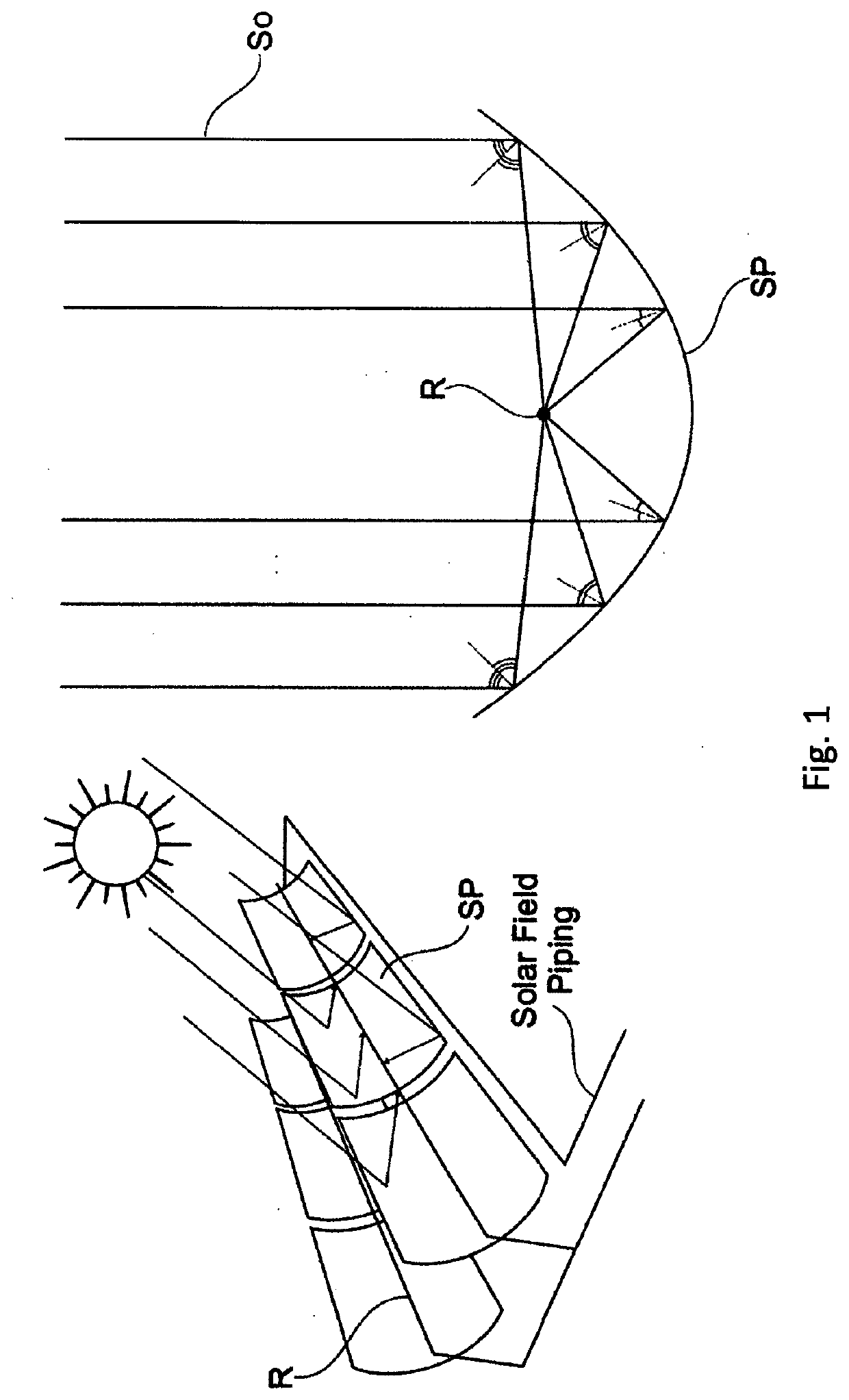
[0102]As discussed above and in the background of the invention, which also relates to features of and related to the present invention, a system of a parabolic trough, i.e. a solar collector assembly (SCA) is exemplarily shown in FIG. 1. A parabolic trough or solar collector assembly (SCA) comprises a linear parabolic reflector SP made of a number of solar collector modules (SCM) fixed together to move as one SP that concentrates light onto a receiver positioned along the reflector's focal line. A receiver tube is positioned directly above the middle of the parabolic mirror at its focal line and filled with a working fluid. The reflector follows the sun during the daylight hours by tracking along a single axis. A working fluid such as molten salt or oil is heated to 150-400° C. (oil) or 200-550° C. (molten salt) as it flows through the receiver, from a receiver entry to a receiver exit. The hot fluid can be used for many purposes. Often, it is piped to a heat engine, which uses the...


PUM


Abstract

Sensor arrangement for tracking a solar collector assembly, the sensor arrangement comprising a housing; said housing comprising an inclination sensor and a camera; said sensor arrangement comprising a shadow receiver; said shadow receiver being arranged and adapted to receive the full shadow of a solar system's receiver tube; wherein the camera and the shadow receiver are arranged such that the camera may sense the full width of the receiver tube's shadow on the shadow receiver.

Description

[0001]This nonprovisional application is a continuation of International Patent Application No. PCT / EP2020 / 050551, filed on Jan. 10, 2020, and claims priority under 35 U.S.C. § 119(a) to European Patent Application No. 19151496.7, which was filed on Jan. 11, 2019 and European Patent Application No. 19179193.8, which was on Jun. 7, 2019, and which are all herein incorporated by reference.BACKGROUND OF THE INVENTIONField of the Invention[0002]The present invention relates to a system and a method for tracking the sun with systems concentrating solar power. The expression Concentrated Solar Power (“CSP”) is commonly used as a generic term for this technology. In such systems and methods, usually the direct solar radiation is focused onto a receiver or solar absorber via reflectors. Since the position of the sun changes over time, the alignment of components of the system has to be accordingly adapted, i.e. the sun has to be tracked with the system.Description of the Background Art[0003...

Claims


Application Information

Patent Timeline
IPC IPC(8): F24S50/20F24S23/74F24S50/40F24S50/80
CPCF24S50/20F24S50/80F24S50/40F24S23/74F24S30/425Y02E10/47F24S40/52
Inventor KIRSCHT, LUKAS
Owner CAMBRAS GMBH
Learn More