Flyback Power Switch Structure for Bridgeless Rectifier

Active Publication Date: 2021-11-11
NANOWATT INC
View PDF0 Cites 0 Cited by
  • Summary
  • Abstract
  • Description
  • Claims
  • Application Information

AI Technical Summary

Benefits of technology

The present invention aims to improve the power supply structure to enhance efficiency and minimize size. It achieves this by reducing energy loss in rectifier diodes and providing better actuation stability and small size, ultimately improving the efficiency and applicability of power converters.

Problems solved by technology

However, the bridge rectifier composed of four diodes D1′˜D4′ and filter 11′ have heavy losses, thus reducing the efficiency.
However, as the two switch components SW2′, SW3′ are not potential to ground, and the drive circuit must be designed as isolated, thus it is difficult to be integrated into the PWM controller.
Further, said structure is provided with an additional primary winding and an additional switch component, so that the snubber design difficulty is increased.
In addition, the main transformer T2′ is enlarged, thus not meeting the requirement for miniaturization.
However, the two switch components SW4′, SW5′ are not switch of potential to ground, and the drive circuit must be isolated, so that it is difficult to be integrated into the PWM controller.
Further, due to AC phase limit, a secondary coil and secondary side rectifying components D7′, D8′ are required, thereby reducing the efficiency.
Therefore, the volume is increased, which does not meet the requirement for miniaturization.
However, the structure still has the energy loss of two diodes.
As it requires two main transformers T4′, T5′, the large volume does not meet the requirement for miniaturization.

Method used


Image

  • Flyback Power Switch Structure for Bridgeless Rectifier
  • Flyback Power Switch Structure for Bridgeless Rectifier
  • Flyback Power Switch Structure for Bridgeless Rectifier

Examples


Embodiment Construction

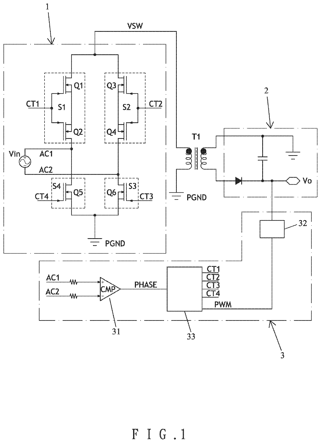
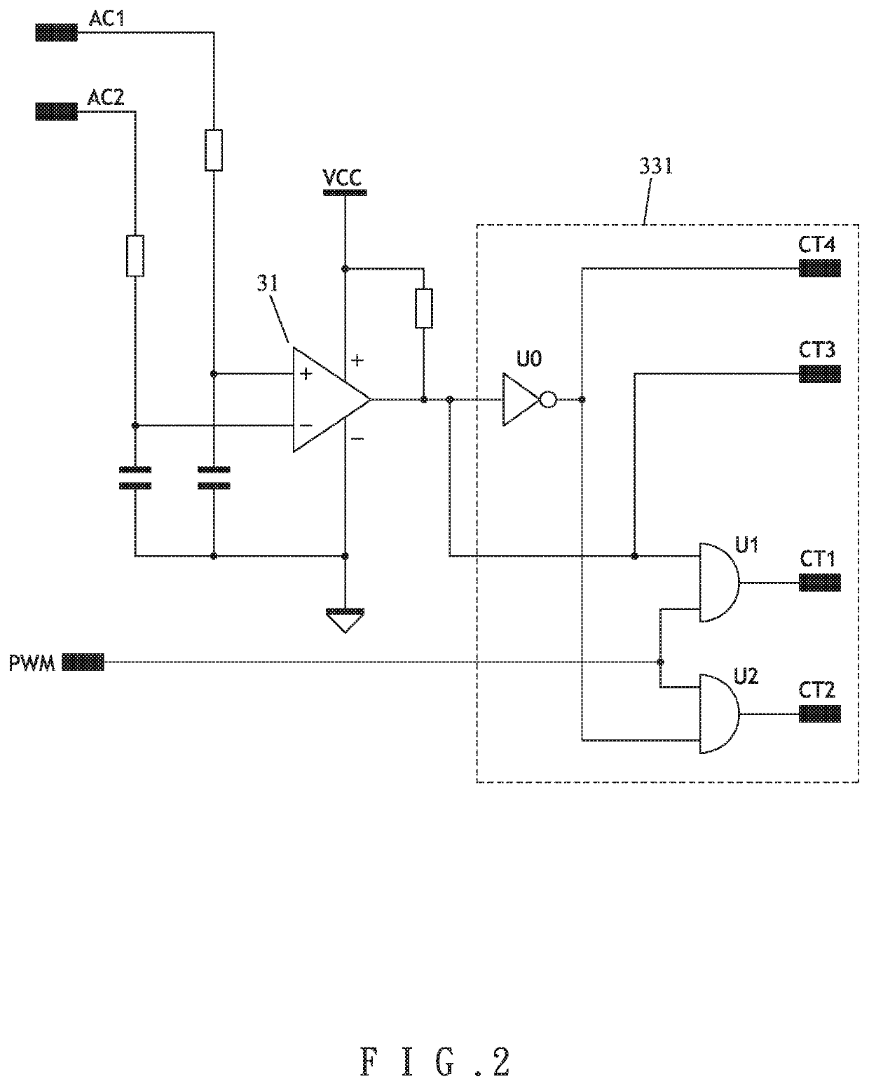
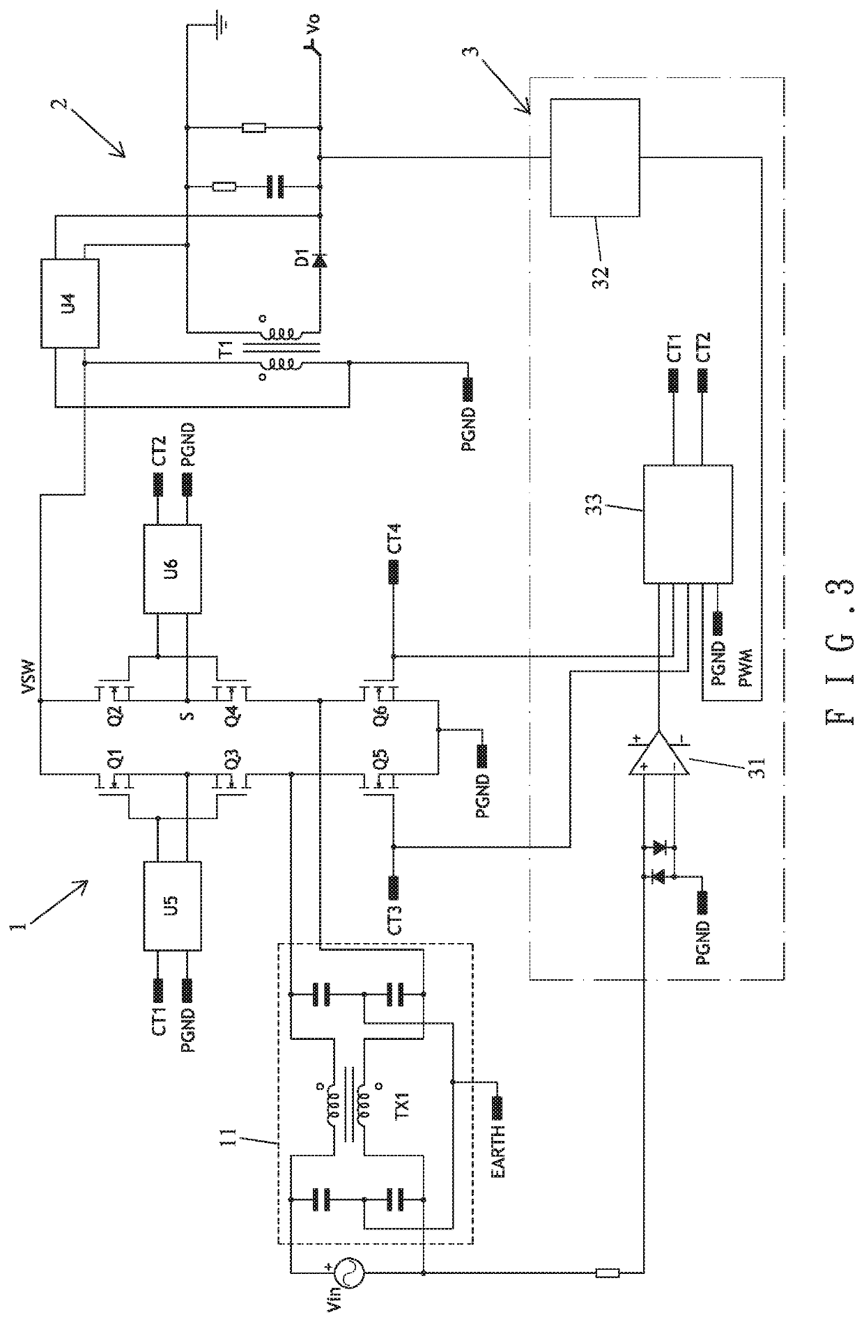
[0026]Referring to FIGS. 1 and 2, the present invention comprises a main transformer T1, a primary side circuit 1, a secondary side circuit 2 and a feedback control circuit 3. Said primary side circuit 1 is electrically connected to input AC power supply Vin and the primary coil of main transformer T1, with a first switch component S1 comprised of the first mosfet Q1 and the second mosfet Q2 oppositely cascaded; a second switch component S2 comprised of the third mosfet Q3 and the fourth mosfet Q4 oppositely cascaded, a third switch component S3 formed of the sixth mosfet Q6, and a fourth switch component S4 formed of the fifth mosfet Q5. S poles of said first and second mosfets Q1, Q2 are connected, and S poles of said third and fourth mosfets Q3, Q4 are connected, so that the internal parasitic diodes of said first and second mosfets Q1, Q2 and said third and fourth mosfets Q3, Q4 can be serially connected oppositely, thus to ensure that the internal parasitic diode can be turned ...


PUM


Abstract

The present invention discloses a flyback power switch structure for bridgeless rectifier, comprising a main transformer, a primary side circuit, a secondary side circuit, and a feedback control circuit. Said main transformer comprises primary coil and secondary coil. Said primary side circuit is connected to the input AC power supply and the primary coil of main transformer, and is provided with a first switch component, a second switch component, a third switch component, and a fourth switch component. Said secondary side circuit is connected to the secondary coil of said main transformer, generating output voltage. Said feedback control circuit is connected to the secondary side circuit and the first, second, third and fourth switch components of primary side circuit, comparing phase signals according to the feedback signals and the first and second terminal voltages of input AC power supply to control the actuation of the first, second, third and fourth switch components. Thereby, the present invention can increase the efficiency and can be easily miniaturized.

Description

BACKGROUND OF INVENTION1. Field of the Invention[0001]The present invention relates generally to a flyback power switch structure for bridgeless rectifier, and more particularly to a power supply structure which can enhance efficiency and can be miniaturized.2. Description of Related Art[0002]The switching power converter is extensively used in a variety of electronic devices. In order to enhance applicability, the present design of power converter aims at miniaturization. FIG. 9 shows a conventional flyback switching power converter, which comprises a main transformer T1′, a primary side circuit 1′ and a secondary side circuit 2′. The primary side circuit 1′ further comprises a bridge rectifier composed of four diodes D1′˜D4′, a filter 11′ and a switch component SW1′. Its advantages include simple structure, the PWM controller (not shown in the figure) can perform switchover work only by driving a switch component SW1′. Said switch component SW1′ is a switch of potential to ground,...

Claims


Application Information

Patent Timeline
IPC IPC(8): H02M3/335H02M1/00
CPCH02M3/33569H02M2001/0048H02M1/00Y02B70/10H02M3/33523H02M5/2932H02M7/4807H02M1/0048
Inventor CHOU, CHUNG-FU
Owner NANOWATT INC
Why Eureka
Try Eureka