Supercharge Your Innovation With Domain-Expert AI Agents!

Pulse-Induced Cyclic Control Lift Propeller

a cyclic control and propeller technology, applied in the field of aeronautical vehicles, can solve the problems of simple devices, high cost, complicated mechanical properties, etc., and achieve the effect of increasing the mass moment of inertia

Pending Publication Date: 2021-11-18
IQINETICS TECH INC
View PDF5 Cites 0 Cited by
  • Summary
  • Abstract
  • Description
  • Claims
  • Application Information

AI Technical Summary

Benefits of technology

This patent describes a system for controlling the speed and torque of an electric motor using a rotating angle sensor and a control mechanism. The system includes a mast connected to the motor, a cyclic pitch inducing rotor device, and a mechanism for increasing the mass moment of inertia for lead-lag stability. The system can also include additional hinges to convert rotor torches into forces. The technical effects of this system include improved control and stability of the motor, as well as more efficient and effective operation.

Problems solved by technology

Swashplates are an effective mechanism for control, but can be mechanically complex and expensive.
The main rotor with these mechanisms is driven by a motor where low frequency changes of motor torque result in thrust changes, while high frequency motor torque changes result in roll or pitch torques.
Though these devices are simpler than a swashplate, they are not without their drawbacks.
Manufacturing complexity is increased by the use of either compliant materials or multiple low-friction hinges.
Furthermore, some designs result in mass imbalance during actuation, causing vibrations.
However, as vehicle sizes scale down, the relative size and complexity of the swashplate mechanism makes its implementation increasingly difficult.
The most notable deficiency is that the quadcopter has an inherently smaller total disc area when compared to a helicopter of equal size because they have four small propellers, which require adequate separation, instead of one (or two in a coaxial setup) large propeller.
While Fujihira achieved underactuation, the stiffness of the compliant hinge inversely determines the control authority and the stiffness has a non-zero practical lower limit on stiffness, resulting in an upper limit on control authority.
However, there are several drawbacks to Paulos' mechanism.
The primary disadvantage is keeping the rotor and propeller system balanced in all flight conditions.
This is further complicated by the hinges having opposite angles, meaning a lag creates more pitch for one blade and a lag creates less pitch for the other.
The blade which increases pitch with increasing lag is less stable than its counterpart in that as the blade lags, the pitch increases, which causes more drag, which in turn creates more lag and then more pitch.
This requires the designer to trim the angles, but this only works for a single operating condition.
Another drawback is that there are two hinges, which is twice as many as necessary.
Additionally, the two hinges present two potential points of failure, and they have a higher chance of failing or binding since the hinges carry multiple loads, namely a thrust load, a radial centripetal force load, and a torque preventing feathering.
While the Paulos device is mechanically simple, it is more complex and has more sources of failure than necessary.
Both of these factors hinder its commercial viability.

Method used


Image

  • Pulse-Induced Cyclic Control Lift Propeller
  • Pulse-Induced Cyclic Control Lift Propeller
  • Pulse-Induced Cyclic Control Lift Propeller

Examples


Embodiment Construction

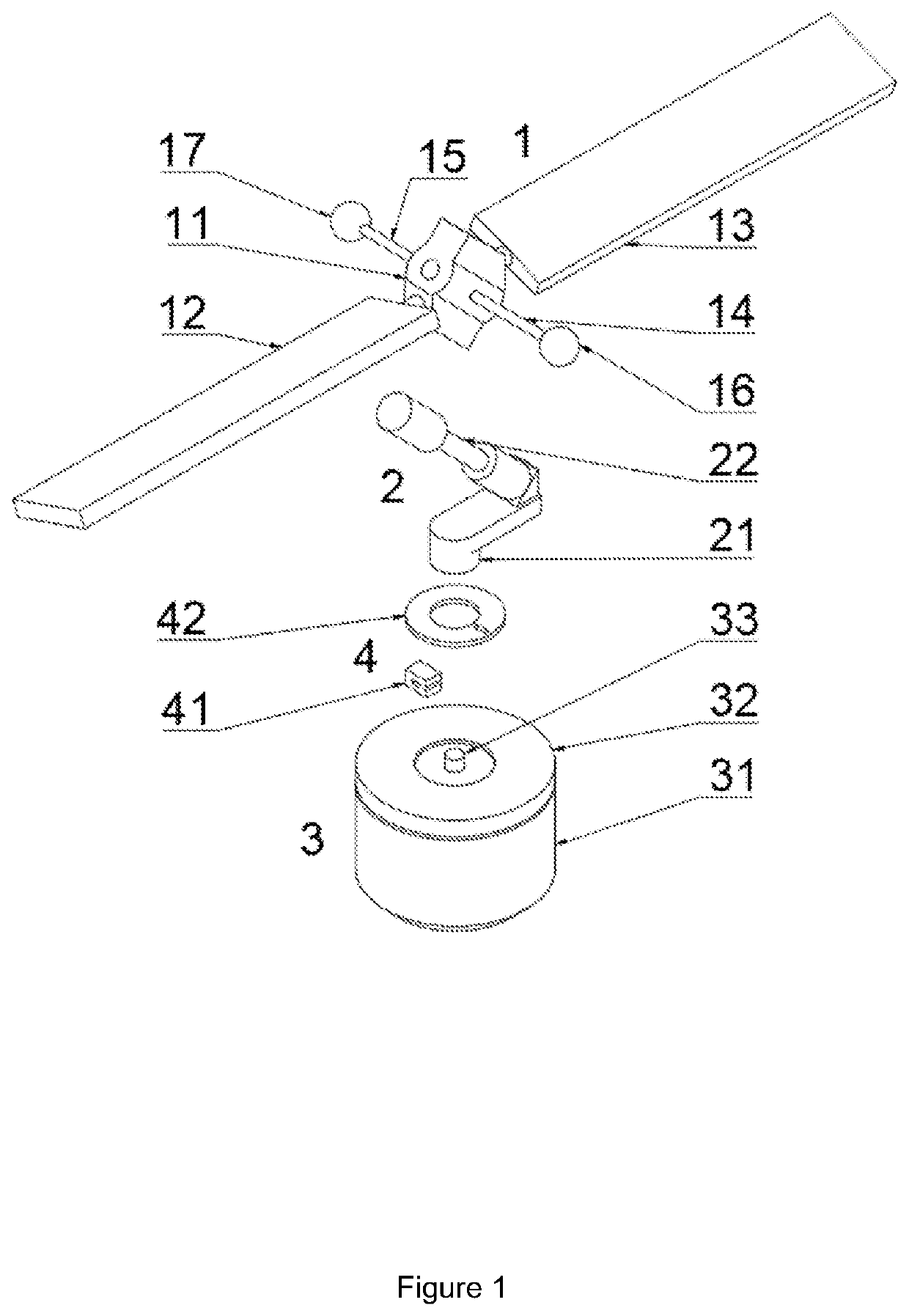
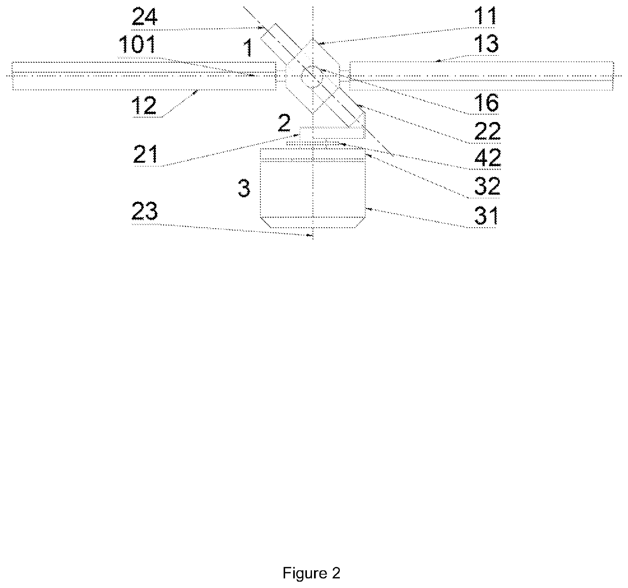
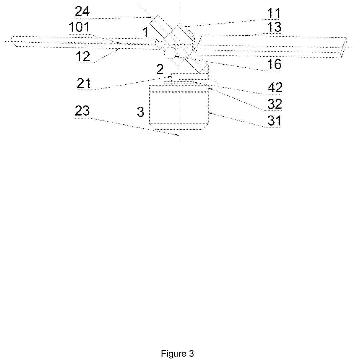
[0032]FIG. 1 is an exemplary illustration of the single-skewed-hinge passive rotor mechanism in an exploded view, according to an aspect of the present disclosure. The components of this mechanism may include propeller assembly 1, mast assembly 2, motor assembly 3, and encoder assembly 4. The propeller assembly 1 may include a hub 11, blades 12 and 13, flybar arms 14 and 15, and flybar weights 16 and 17. The mast assembly 2 may include a mast 21 and a hinge 22. The motor assembly 3 may include a rotor 31, a stator 32, and a rotor shaft 33. The connection between the rotor and rotor shaft is assumed to be rigid. The encoder assembly 4 may include a fixed sensor 41 and a rotating sensed object 42.

[0033]The connection between the mast 21 and the hub 11 may be a single hinge 22 skewed nominally, but not necessarily, at 45 degrees from the vertical mast spin axis towards the feathering axis of the blades 12 and 13. The hub 11 may be attached to components that increase the mass moment of...


PUM


Abstract

The present application relates to a propulsion device having a motor, a mast connected to the motor, an angle sensing device detecting the angle of the mast, a controller receiving the angle of the mast as an input and outputting a motor torque signal to the motor in response thereto, a hub attached to the mast via a single skewed hinge, and a propeller assembly with one or more blades connected to a hub.

Description

CROSS-REFERENCE TO RELATED APPLICATIONS[0001]This application claims the benefit of U.S. Pat. App. Ser. No. 63 / 026,355 filed May 18, 2020, the contents of which are incorporated by reference in its entirety.TECHNICAL FIELD[0002]The technical field relates to aerial vehicles, specifically those involving passive control mechanisms for variable cyclic pitch propellers and motor pulsing technology.BACKGROUND OF THE INVENTION[0003]Propeller-based propulsion systems have been around for more than a century, and the evolution of aerial vehicles has given rise to a number of propeller configurations and control methods. Helicopters traditionally use a swashplate to control the vehicle's roll and pitch and a tail rotor to control the vehicle's yaw. Swashplates are an effective mechanism for control, but can be mechanically complex and expensive. In contrast, quadrotors have recently become a popular vehicle design due to their mechanical simplicity. These vehicles, however, require four dri...

Claims


Application Information

Patent Timeline
Patent Type & Authority Applications(United States)
IPC IPC(8): B64C27/39B64C27/605
CPCB64C27/39B64C27/605B64C27/625
Inventor PICCOLI, MATTHEW
Owner IQINETICS TECH INC
Features
  • R&D
  • Intellectual Property
  • Life Sciences
  • Materials
  • Tech Scout
  • Unparalleled Data Quality
  • Higher Quality Content
  • 60% Fewer Hallucinations
Learn More