
Systems and methods to remove input voltage dependency in a power converter

a power converter and input voltage technology, applied in the field of telecommunications, can solve the problems of increasing the cost of the power converter, increasing the stress on the components of the system, and increasing the magnitude of the negative supply voltag

Pending Publication Date: 2021-11-18
MICROCHIP TECH INC
View PDF4 Cites 1 Cited by
  • Summary
  • Abstract
  • Description
  • Claims
  • Application Information

AI Technical Summary

Benefits of technology

The present invention provides a better way to get both low and high voltages from one input. The effect of the input voltage on the high voltage is reduced, and the high voltage is a multiple of the low voltage.

Problems solved by technology

The contribution of the input voltage magnitude may be enough to increase the magnitude of the high negative supply voltage to a level requiring higher voltage-rated components, which are often more expensive, thereby increasing the cost of the power converter.
Additionally, a higher negative supply voltage magnitude increases the stress on the components of the system.

Method used


Image

  • Systems and methods to remove input voltage dependency in a power converter
  • Systems and methods to remove input voltage dependency in a power converter
  • Systems and methods to remove input voltage dependency in a power converter

Examples


Embodiment Construction

[0020]Persons of ordinary skill in the art will realize that the following description is illustrative only and not in any way limiting. Other embodiments will readily suggest themselves to such skilled persons.

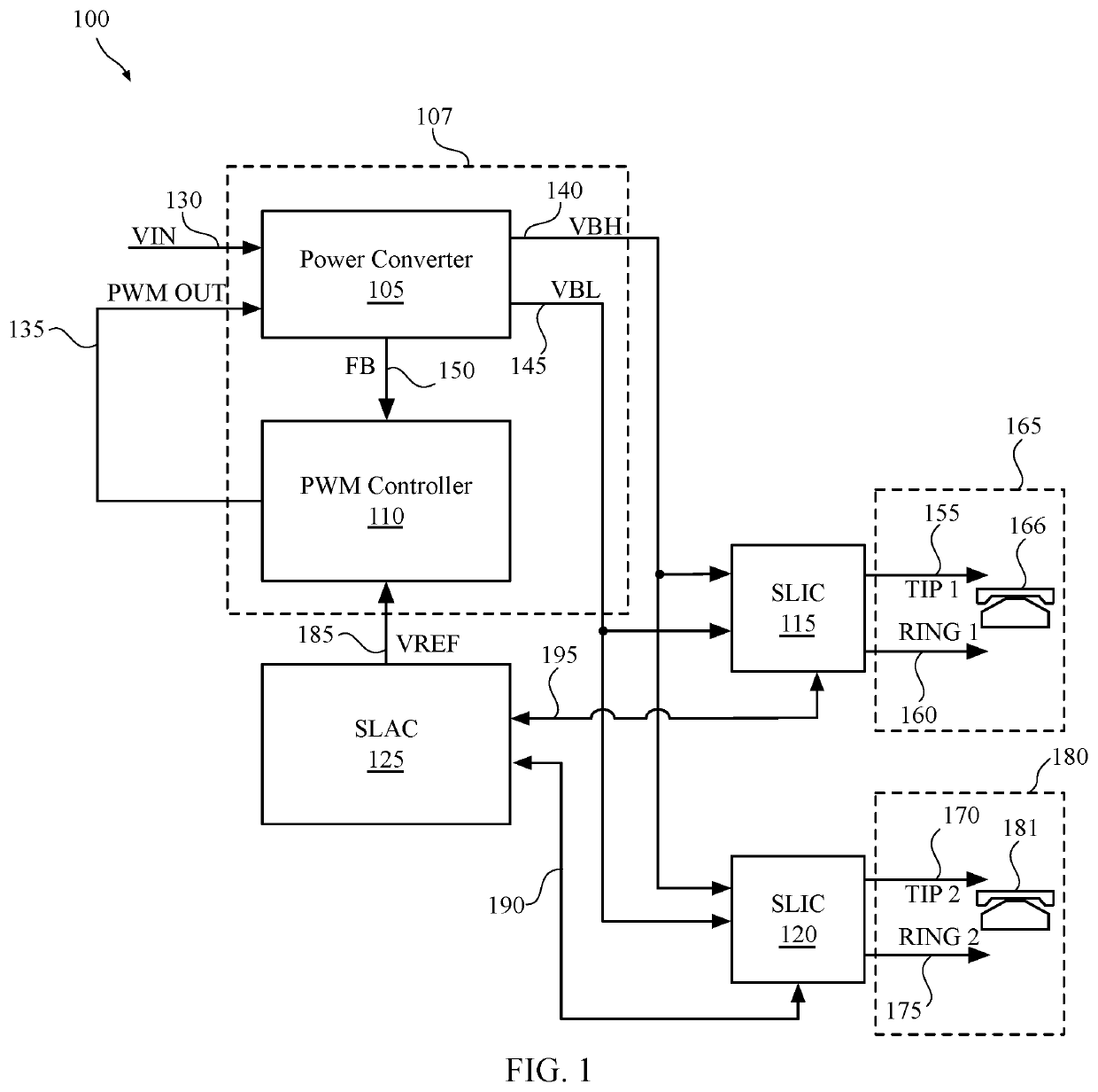
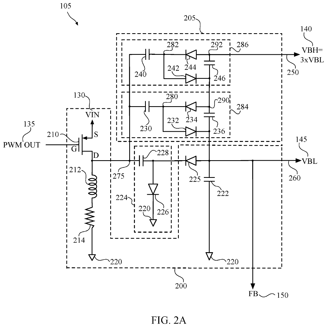
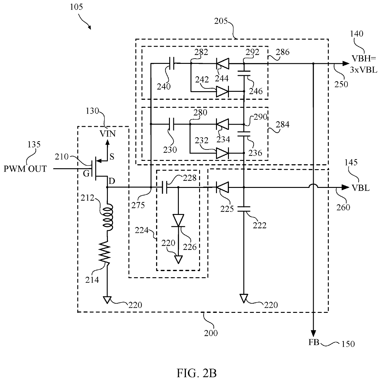
[0021]In various embodiments, the present invention provides a system and method for preventing a change in magnitude of an input voltage of a voltage converter from contributing to a change in magnitude of a high supply voltage generated by a boost circuit of the voltage converter. In particular, the voltage converter generates both a high supply voltage and a supply output voltage that are provided to one or more SLICs in a sub scriber line telecommunication system.

[0022]FIG. 1 is a simplified block diagram of a communication system 100 including a subscriber line audio-processing circuit (SLAC) 125, two subscriber line interface circuits (SLICs) 115, 120, and a voltage regulator 107. The voltage regulator 107 includes a power converter 105 and a pulse-width modulated (PWM)...


PUM


Abstract

A system and method for generating a low supply voltage and a high supply voltage from an input voltage, wherein the dependency of the high supply voltage magnitude on the magnitude of the input voltage is removed and the resulting high supply voltage magnitude is a multiple of the low supply voltage magnitude. The low supply voltage and the high voltage may be implemented in a power converter of a communication system comprising a plurality of subscriber line interface circuits (SLICs).

Description

CROSS-REFERENCE TO RELATED APPLICATIONS[0001]The present application claims priority to U.S. Provisional Patent Application Ser. No. 63 / 025,120, filed on May 14, 2020, the contents of which are incorporated by reference herein in their entirety.BACKGROUND[0002]The present invention relates to telecommunications, and more particularly, to a power converter for generating supply voltages to support one or more subscriber lines.[0003]In telecommunications systems, signals are transmitted between a subscriber station and a central switching office using a two-wire bi-directional communication channel. A line card typically connects the subscriber station to the central switching office, wherein the line card typically includes at least one subscriber line interface circuit (SLIC) and a subscriber line audio-processing circuit (SLAC).[0004]The SLIC provides an interface between a low-voltage signal path in a telephone central office and a high-voltage telephone subscriber line. The SLIC ...

Claims


Application Information

Patent Timeline
Patent Type & Authority Applications(United States)
IPC IPC(8): H02M3/158H04Q1/28
CPCH02M3/158H04Q1/28H02M1/009H02M1/0095H02M3/071H02M3/156
Inventor RABB, JASON
Owner MICROCHIP TECH INC
Learn More