
Blood Pumping Device

a technology of blood pumping device and blood vessel, which is applied in the direction of blood pump, circulatory assistance device, intravenous device, etc., can solve the problems of heart failure patients dying, stroke, other damage, death, etc., and achieves the effect of positive physiological

Pending Publication Date: 2021-11-25
SCANDINAVIAN REAL HEART
View PDF0 Cites 0 Cited by
  • Summary
  • Abstract
  • Description
  • Claims
  • Application Information

AI Technical Summary

Benefits of technology

The blood pumping device described in this patent is designed to mimic the natural heart, which helps to minimize complications when using it as a replacement for a damaged heart. This makes it a safer and more effective treatment option for patients with heart disease.

Problems solved by technology

The end result of such diseases may be heart failure which means that the heart has lost its ability to pump enough blood to the lungs and body tissues.
However, due to a lack of sufficient number of donor hearts the majority of advanced heart failure patients die while waiting for a heart transplant operation.
One major complication of existing TAHs currently approved on the market is the formation of blood clots which can cause strokes, other damages, and even death when they form inside vital organs of the body as embolisms.
Other complications may be bleedings and infections.
These complications arise also when the TAHs are used for only a short time as a bridge when awaiting heart transplantation.
None of the existing TAHs are constructed in accordance with the physiology and anatomy of the natural human heart and this may be why none of these TAHs is able to permanently replace the function of a human heart.

Method used


Image

  • Blood Pumping Device
  • Blood Pumping Device
  • Blood Pumping Device

Examples


Embodiment Construction

[0109]Blood Pumping Device with Four Chambers

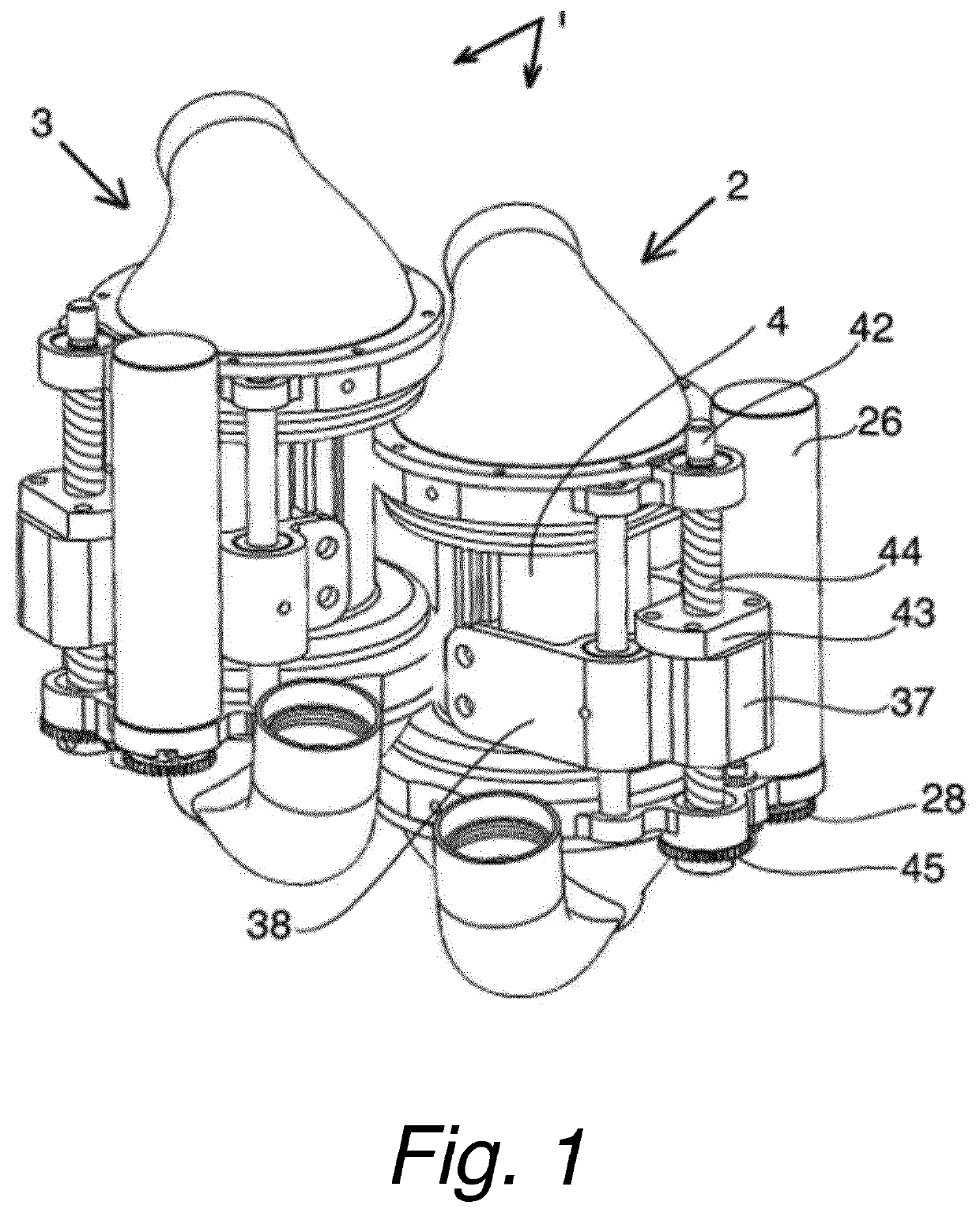
[0110]A blood pumping device 1 having four chambers is disclosed in FIG. 1. The four-chambered blood pumping device 1 comprises two pumps, a first pump 2 and a second pump 3, and a first and second pump actuating means for inducing a blood flow in a body's circulatory system. The first and the second pumps 2, 3 are identical in their construction and the general design of a pump of the four-chambered blood pumping device 1 will now be described in detail.

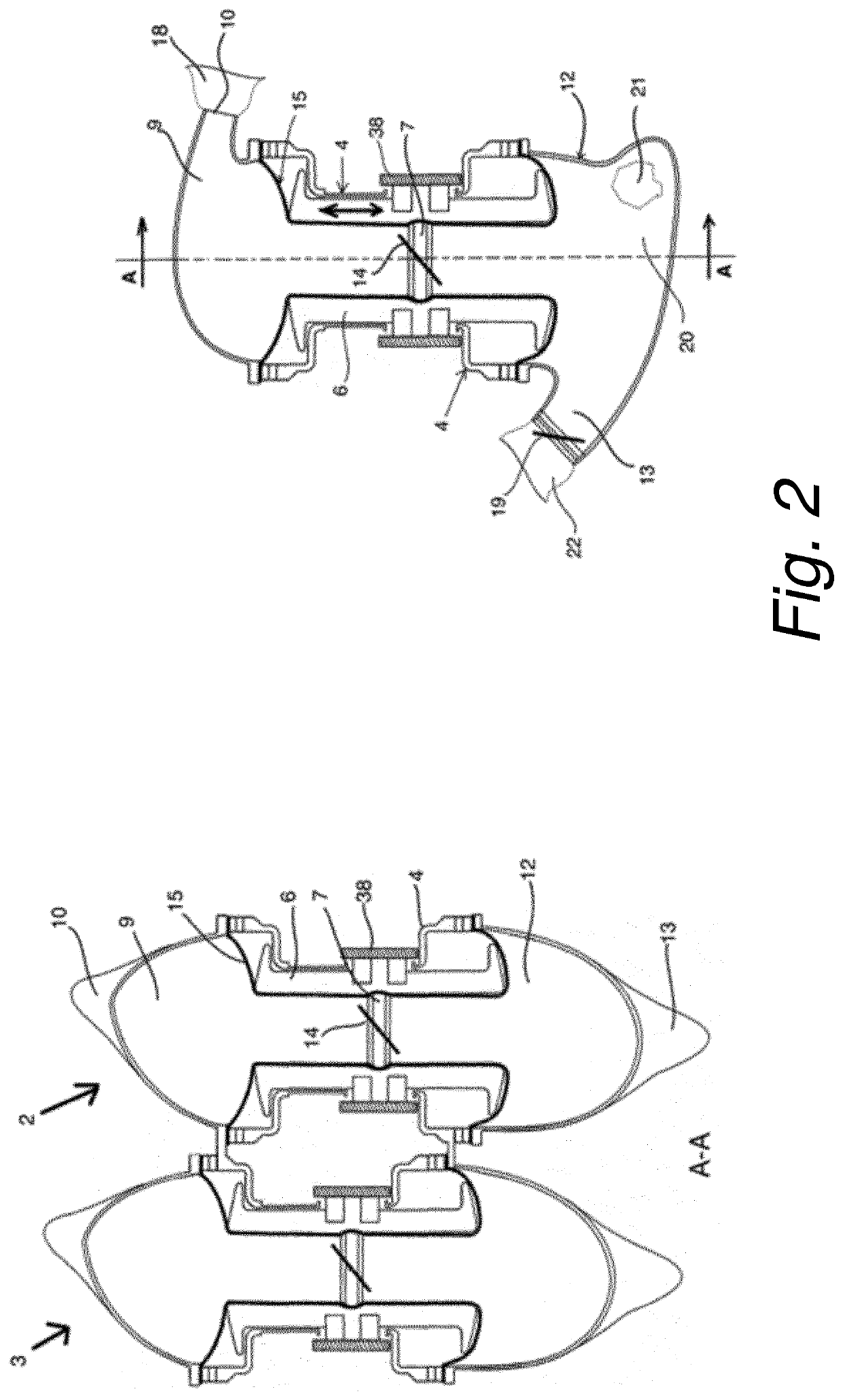
[0111]Each pump comprises an upper chamber 9 and a lower chamber 12, see FIG. 2 wherein a cross-sectional view of a four-chambered blood pumping device is shown. The upper chamber 9 has an inlet channel 10 which allows blood to enter the upper chamber 9. Said upper chamber corresponds to an atrium of the natural heart. The lower chamber 12 is provided with an outlet channel 13 which allows blood to exit the lower chamber 12. Said lower chamber 12 corresponds to a ventricle of the natural ...


PUM


Abstract

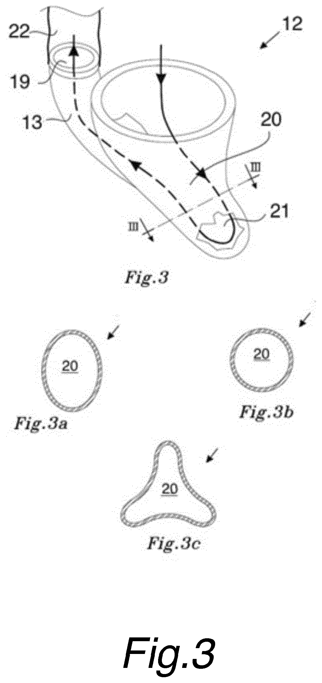
A blood pumping device having at least a first pump and a second pump, and a first and second pump actuating means for inducing a blood flow in a body's circulatory system is disclosed. Each pump comprises one upper chamber having an inlet channel and one lower chamber having an outlet channel. The upper and lower chambers are separated by a movable valve plane provided with a valve. The pump actuating means are configured to apply a movement to said valve plane in an upward and downward direction between said upper and lower chambers in response to control signals from a control unit, such that when said valve plane moves in an upward direction the valve provided in the valve plane is in an open position allowing a flow of blood from the upper chamber to the lower chamber, and when the valve plane moves in a downward direction the valve is in the closed position and blood is ejected from the lower chamber through the outlet channel. The bottom part of the bag portion has a shape that makes a turn of between 110° to 150° to cause blood entering the lower chamber to hit the stopping surface and come to a sudden stop, wherein the turn causes the flow of blood along the inner surface of the bag portion to abruptly change; and directs blood at the stopping surface to continue flowing along the outlet channel.

Description

TECHNICAL FIELD[0001]The present disclosure relates to a blood pumping device such as a Total Artificial Heart (TAH) which may totally or partly replace the function of a natural heart. The disclosure also relates to a blood pumping device which may be permanently or temporarily be used as a left ventricular assist (LVAD), right ventricular assist device (RVAD) or cardiopulmonary bypass device.BACKGROUND OF THE INVENTION[0002]The main function of the heart in the human body is to circulate blood through the blood vessels in order to transport oxygen, nutrition, and waste products to and from body cells. Many diseases may affect the heart such as myocardial infarction, hypertension, valve insufficiency and various heart muscle diseases. The end result of such diseases may be heart failure which means that the heart has lost its ability to pump enough blood to the lungs and body tissues.[0003]The symptoms of heart failure are shortness of breath, edema and fatigue. The only treatment ...

Claims


Application Information

Patent Timeline
Patent Type & Authority Applications(United States)
IPC IPC(8): A61M60/894A61M60/148A61M60/258A61M1/36
CPCA61M60/894A61M60/148A61M60/40A61M1/3666A61M60/258A61M60/113A61M60/896A61M60/178A61M60/183A61M60/196A61M60/38A61M60/443A61M60/835A61M60/427A61M60/462A61M60/446A61M60/876A61M1/3623A61M2205/18A61M2205/3331A61M2205/3368A61M2205/50A61M2205/8206A61M2205/8243
Inventor NAJAR, AZAD
Owner SCANDINAVIAN REAL HEART
Learn More