Eureka AIR delivers breakthrough ideas for toughest innovation challenges, trusted by R&D personnel around the world.

On-board component abnormal site identifying method, on-board component abnormal site identifying system, on-board component abnormal site identifying apparatus, on-board component abnormal site report control apparatus, and vehicle control apparatus

Active Publication Date: 2021-11-25
TOYOTA JIDOSHA KK
View PDF0 Cites 0 Cited by
  • Summary
  • Abstract
  • Description
  • Claims
  • Application Information

AI Technical Summary

Benefits of technology

The present disclosure provides an on-board component abnormal site identifying method that uses variables to indicate the presence and concentration of foreign substances in the oil. This method increases the accuracy of identifying abnormal sites in the oil flowing through on-board components. Additionally, the method includes a diagnosis variable that helps to identify the cause of abnormalities in the oil flow, such as the solenoid valve or friction engagement element. By using this method, the number of training data needed for training the mapping data is reduced, and the accuracy of calculating the value of the output variable is increased, even in fewer intermediate layers and dimensions of the input variables.

Problems solved by technology

Thus, it is difficult for the apparatus described above to identify an abnormal site when an abnormality occurs in the transmission.
Therefore, when the color of the oil is a typical color over a long period of use, there is a strong possibility of the abnormality in the oil.
One of the reasons why the color of the oil is a typical color over a long period of use is that the traveling load is excessively large.
When the abnormality occurs in the stepped transmission, there is a tendency toward an increase in the deviation between the reference rotation speed and the actual rotation speed of the rotational shaft of the rotating machine when the gear ratio is changed.
In the case where the deviation between the reference rotation speed and the actual rotation speed of the rotational shaft of the rotating machine increases when the gear ratio is changed, it is difficult to determine, based on behavior of the rotation speed alone, whether the cause of the increase in the deviation is the solenoid valve or the friction engagement element.

Method used


Image

  • On-board component abnormal site identifying method, on-board component abnormal site identifying system, on-board component abnormal site identifying apparatus, on-board component abnormal site report control apparatus, and vehicle control apparatus
  • On-board component abnormal site identifying method, on-board component abnormal site identifying system, on-board component abnormal site identifying apparatus, on-board component abnormal site report control apparatus, and vehicle control apparatus
  • On-board component abnormal site identifying method, on-board component abnormal site identifying system, on-board component abnormal site identifying apparatus, on-board component abnormal site report control apparatus, and vehicle control apparatus

Examples


first embodiment

[0050]An on-board component abnormal site identifying method according to a first embodiment is described below with reference to the drawings.

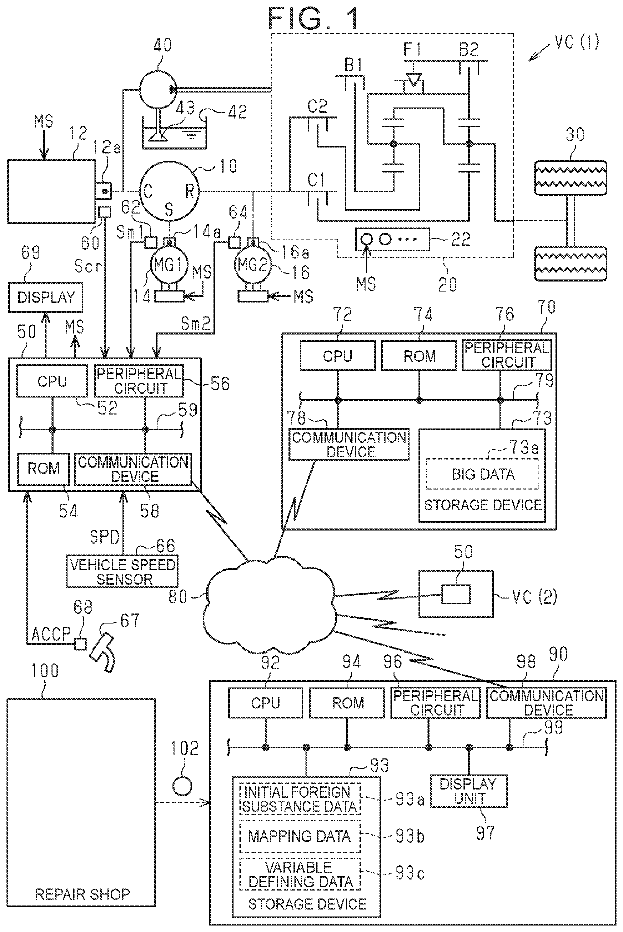
[0051]A vehicle VC(1) illustrated in FIG. 1 is a series-parallel hybrid vehicle. A power split device 10 of the vehicle VC(1) includes a planetary gearing mechanism including a sun gear S, a carrier C, and a ring gear R. A crankshaft 12a of an internal combustion engine 12 is mechanically coupled to the carrier C of the power split device 10. A rotational shaft 14a of a first motor generator 14 is mechanically coupled to the sun gear S. A rotational shaft 16a of a second motor generator 16 is mechanically coupled to the ring gear R. Driving wheels 30 are mechanically coupled to the ring gear R via a stepped transmission 20 including clutches C1 and C2, brakes B1 and B2, and a one-way clutch F1.

[0052]The transmission 20 is supplied with hydraulic oil ejected from an oil pump 40 having a driven shaft mechanically coupled to the carrier C of the...

second embodiment

[0111]A second embodiment is described below with reference to the drawings, focusing on a difference from the first embodiment.

[0112]In the embodiment described above, the concentrations of the foreign substances in the oil are detected and added to the input variables of the mapping. The color of the oil changes depending on the concentrations of the foreign substances in the oil. In this embodiment, the information on the foreign substances in the oil is substituted by the color of the oil.

[0113]FIG. 10 illustrates details of the process of S48 according to this embodiment. The CPU 92 executes a program stored in the ROM 94, whereby the process illustrated in FIG. 10 is implemented. In FIG. 10, processes corresponding to the processes illustrated in FIG. 5 are represented by the same step numbers for convenience, and their description is omitted.

[0114]In a series of processes illustrated in FIG. 10, the CPU 92 first calculates a surge amount maximum value ΔNm2max and a surge time...

third embodiment

[0122]A third embodiment is described below with reference to the drawings, focusing on a difference from the second embodiment.

[0123]FIG. 12 illustrates details of the process of S48 according to this embodiment. The CPU 92 executes a program stored in the ROM 94, whereby the process illustrated in FIG. 12 is implemented. In FIG. 12, processes corresponding to the processes illustrated in FIG. 10 are represented by the same step numbers for convenience, and their description is omitted.

[0124]In a series of processes illustrated in FIG. 12, when the process of S50a is completed, the CPU 92 acquires a corrected color variable Vocc (S52b). Also in this embodiment, the color variable Vocc is reported from the repair shop 100. The color variable Vocc is obtained by a method in which the judged color of the sampled oil is quantified based on information obtained at the repair shop. That is, the color variable Vocc is equivalent to a variable obtained by a method in which the color variab...


PUM


Abstract

An on-board component abnormal site identifying method includes executing an acquisition process, a calculation process, and a reporting process by an execution device. The acquisition process is a process for acquiring, by the execution device, values of input variables. The mapping includes, as the input variables, a foreign substance variable, and includes, as an output variable, an abnormal site variable. The calculation process is a process for calculating, by the execution device, a value of the abnormal site variable by inputting, to the mapping, the values of the input variables acquired through the acquisition process. The reporting process is a process for reporting, by the execution device, a calculation result of the calculation process by operating a reporting device.

Description

CROSS-REFERENCE TO RELATED APPLICATION[0001]This application claims priority to Japanese Patent Application No. 2020-087962 filed on May 20, 2020, incorporated herein by reference in its entirety.BACKGROUND1. Technical Field[0002]The present disclosure relates to an on-board component abnormal site identifying method, an on-board component abnormal site identifying system, an on-board component abnormal site identifying apparatus, an on-board component abnormal site report control apparatus, and a vehicle control apparatus.2. Description of Related Art[0003]For example, Japanese Unexamined Patent Application Publication No. 2000-240784 (JP 2000-240784 A) describes an apparatus configured to detect a malfunction in a solenoid valve of a transmission based on a change in a rotation speed of an internal combustion engine during gear shifting.SUMMARY[0004]The site where an abnormality may occur in the transmission is not always the solenoid valve. Thus, it is difficult for the apparatus...

Claims


Application Information

Patent Timeline
IPC IPC(8): F16H61/12F16H57/04F16H61/68F16H59/42F16H59/72
CPCF16H61/12F16H57/0405F16H61/68F16H2061/1268F16H59/72F16H2061/128F16H59/42B60R16/0232B60R16/0234F16H2025/2084F16H3/66F16H2003/445F16H2200/2007F16H2200/2041F16H2200/2066F16H2200/2082
Inventor OKUDA, KOICHITABATA, ATSUSHIFUJII, KOTAIMAMURA, KEN
Owner TOYOTA JIDOSHA KK
Why Eureka
Eureka Blog
Learn More