Fuel cell system
a fuel cell and system technology, applied in the field of fuel cell systems, can solve the problems of difficult thawing of freezing by warm-up operation, insufficient reaction gas flow inside the fuel cell, and inability to achieve the effect of reducing the power consumption of the fuel cell system, eliminating the freezing of the fuel cell, and increasing the power consumption
- Summary
- Abstract
- Description
- Claims
- Application Information
AI Technical Summary
Benefits of technology
Problems solved by technology
Method used
Image
Examples
first embodiment
A. First Embodiment
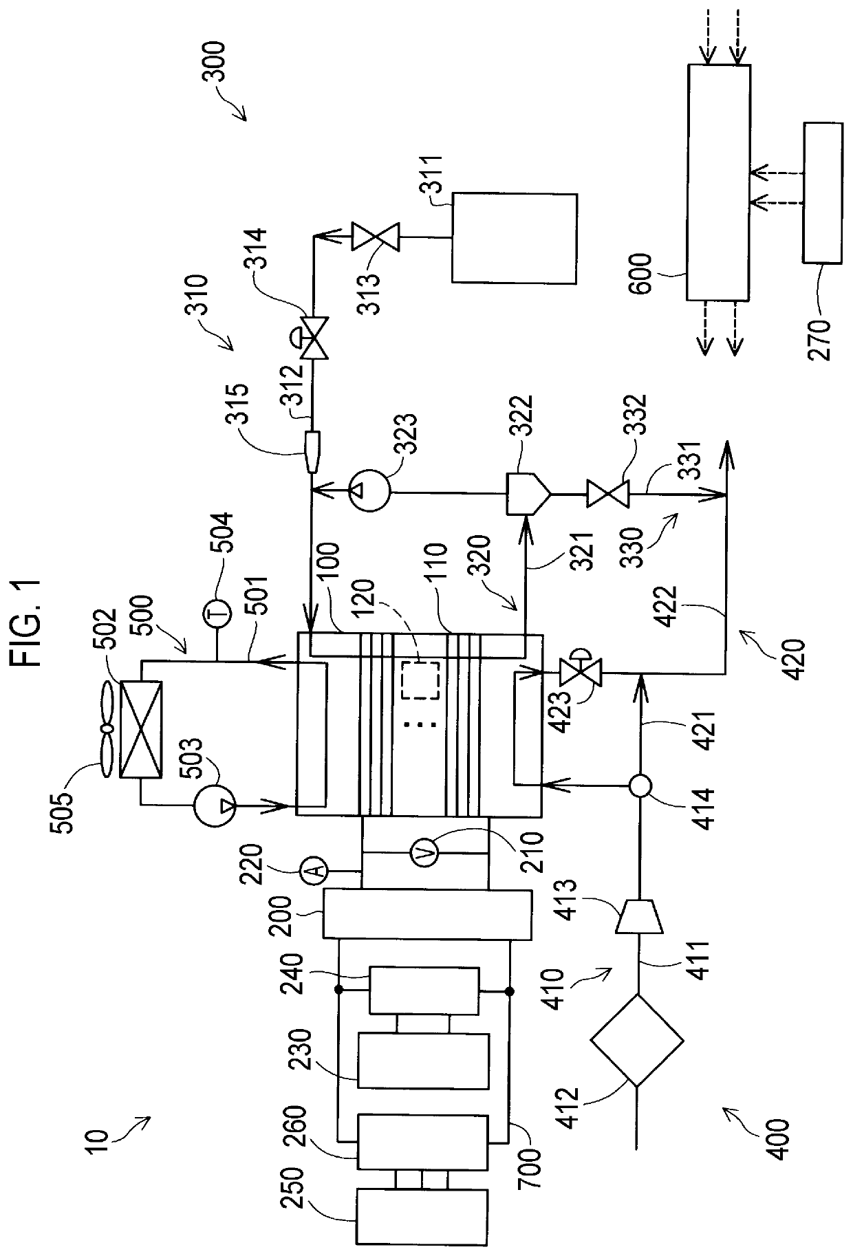
[0015]FIG. 1 is a schematic configuration diagram of a fuel cell system 10 as a first embodiment. The fuel cell system 10 includes a fuel cell 100, a DC / DC converter 200, a voltage sensor 210, a current sensor 220, a secondary battery 230, a secondary battery converter 240, a load device 250, a DC / AC inverter 260, an operation switch 270, a fuel gas supply and discharge unit 300, an oxidation gas supply and discharge unit 400, a refrigerant circulation unit 500, and a controller 600. In the fuel cell system 10, the fuel cell 100 and the secondary battery 230 can each supply power to the load device 250 independently. Alternatively, both the fuel cell 100 and the secondary battery 230 can simultaneously supply power to the load device 250.
[0016]The fuel cell 100 and the load device250 are connected through the DC / DC converter and wiring 700. The DC / DC converter 200 and the secondary battery converter 240 are connected in parallel to the wiring 700.
[0017]The fuel ce...
second embodiment
B. Second Embodiment
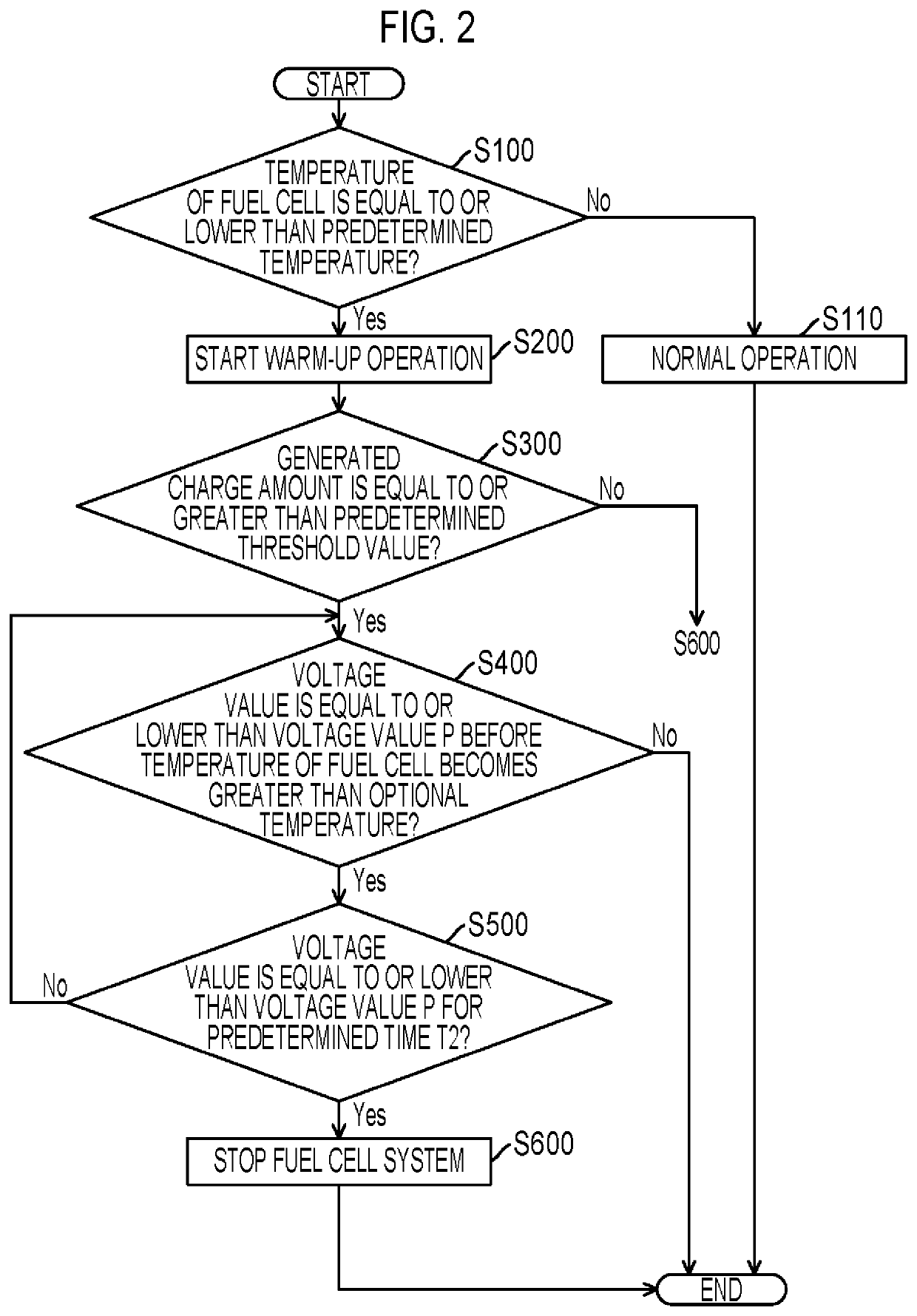
[0052]FIG. 4 is a flowchart showing a process of determining whether or not operation is possible, the process being executed by the controller 600 according to a second embodiment. Since the fuel cell system 10 of the second embodiment has the same configuration as that of the fuel cell system 10 shown in FIG. 1, detailed description thereof will be omitted using the same reference numerals. In the flowchart of the second embodiment shown in FIG. 4, steps common to those in FIG. 2 are denoted by the same step numbers, and detailed description thereof will be omitted. The second embodiment is different from the first embodiment in that predetermined time T2 is set by the controller 600 according to the temperature of the fuel cell 100.
[0053]FIG. 5 is a table showing a freezing determination time according to the temperature of the fuel cell 100. In the first embodiment, predetermined time T2 in Step 5500 is constant regardless of the temperature of the fuel cell ...
PUM
| Property | Measurement | Unit |
|---|---|---|
| time T2 | aaaaa | aaaaa |
| time T2 | aaaaa | aaaaa |
| output current | aaaaa | aaaaa |
Abstract
Description
Claims
Application Information
 - R&D
- Intellectual Property
- Life Sciences
- Materials
- Tech Scout
- Unparalleled Data Quality
- Higher Quality Content
- 60% Fewer Hallucinations
Browse by: Latest US Patents, China's latest patents, Technical Efficacy Thesaurus, Application Domain, Technology Topic, Popular Technical Reports.
© 2025 PatSnap. All rights reserved.Legal|Privacy policy|Modern Slavery Act Transparency Statement|Sitemap|About US| Contact US: help@patsnap.com


