
Nasal smoke evacuator

a smoke evacuator and nasal tube technology, applied in the field of surgery, can solve the problems of aerosol production, droplet, tissue to be burned away, smoke plume being produced at the operative site, etc., and achieve the effect of effectively evacuating smoke plumes and effectively capturing and removing aerosols

Pending Publication Date: 2021-12-16
BURBAN JOHN H +5
View PDF0 Cites 0 Cited by
  • Summary
  • Abstract
  • Description
  • Claims
  • Application Information

AI Technical Summary

Benefits of technology

The present invention is a device and technique for safely removing smoke, vapor, and other particles from the nasal cavity during surgery. The device includes a tube placed in the opposite nasal cavity that is sealed to prevent air from escaping. This tube is connected to a vacuum, which pulls the air and particles from the surgery side of the nasal cavity. The technique involves using the device to capture and remove the particles, which can improve the air quality in the surgical environment and promote patient safety.

Problems solved by technology

Many surgical procedures result in the creation of aerosols, smoke, droplets
In many cases, the tissue is destroyed by applying heat via electrosurgery or laser to the tissue causing the tissue to be burned away.
This heat from this procedure typically vaporizes the intracellular fluid, bursting the cell membranes and results in a plume of smoke being produced at the operative site as the tissue is destroyed.
However, the smoke aerosols and particulates are small enough in size to potentially cause lung and eye irritation.
But it is known that the smoke aerosols and particulates may include viable microbial and viral contaminants as well as destroyed tissue.
This is especially problematic in endoscopic sinus surgery / nasal surgery.
Trying to hold a suction close to the nostril during surgery is challenging as the surgeon needs room to move the endoscope and surgical tools, so this limits the amount of plume that can be captured.
The smoke may not only cause buildup, reduced visibility, or damage or desensitize equipment, but the air-borne residue may contain viable viruses or other infectious mass.
An air filter disposed in the primary channel has a tendency to block the air that would otherwise cool the air pump.
These systems are not easily used in sinus and nasal surgery.
They are bulky, get in the way of the surgeon performing the surgery, require the purchase of new equipment to operate them.
This creates potential risks to the surgeon and operating staff if all the plume is not captured.

Method used


Image

  • Nasal smoke evacuator
  • Nasal smoke evacuator
  • Nasal smoke evacuator

Examples


Embodiment Construction

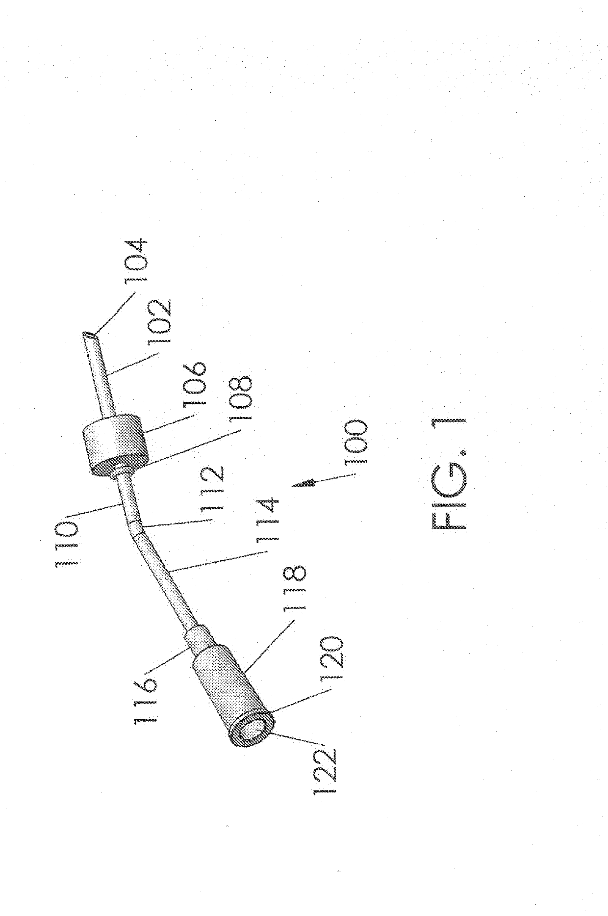
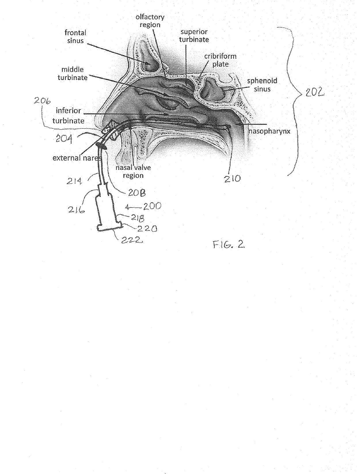
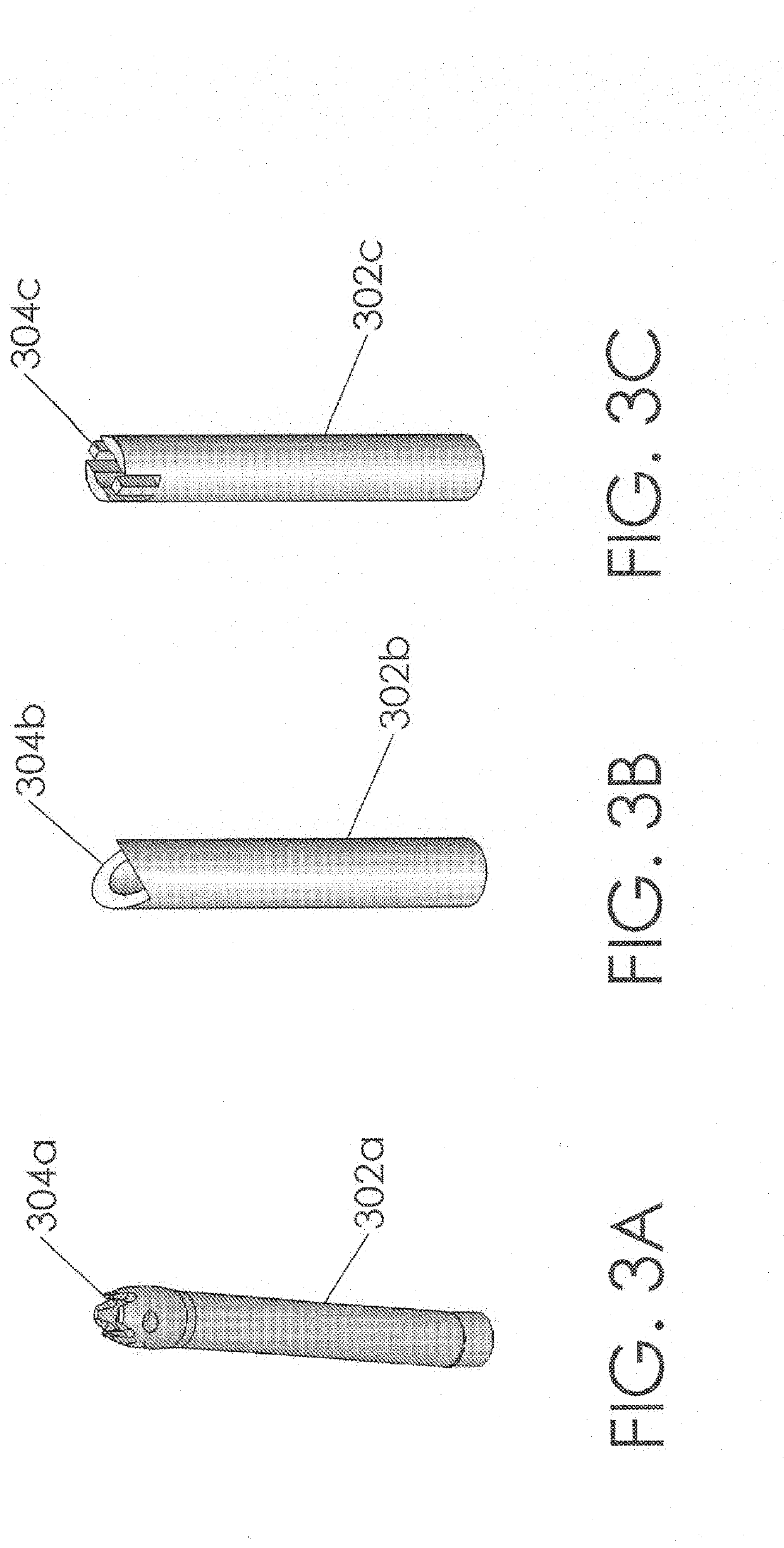
[0037]A system and method to remove smoke, (aerosols, droplets, or other particles during sinus surgery (this may be laser heat, probe heat, resistive electrical heat, abrasive, flame or friction heat and or any other procedure which generates aerosols, droplets or other particles). In one embodiment of the invention, the method includes providing an aerosol evacuator having an elongate tube. The tube may be flexible or rigid. It may be made of polymeric or metal materials.

[0038]A sealing member is connected to the evacuator tube, the sealing member having a proximal side and a distal side. The proximal end of the tube must be long enough to reach a connection to a vacuum source. The sealing member has a central lumen.

[0039]The sealing member is inserted into the nares during or before the surgery, which is to be done on an interior portion of the patient's body, in a cavity in gas-fluid communication with the nasal cavity where the evacuator tube is inserted. The sealing member sho...


PUM


Abstract

A method and means effectively evacuates smoke plumes, vapors, aerosol release, mists, tissue and small particles produced from an operative nasal cavity and any other gas- or air-borne materials provided in or produced in the surgical environment. To this end, an evacuator tube is placed in the contralateral (suction) nasal cavity surrounded by a sealing member which blocks the space between the evacuator tube and nares and / or nasal vestibule.

Description

RELATED APPLICATIONS DATA[0001]This application claims priority from two U.S. Provisional patent applications, U.S. Ser. No. 63 / 050,162, Filed 10 Jul. 2020 and Titled NASAL SMOKE EVACUATOR; and U.S. Ser. No. 63 / 037,246, filed 10 Jun. 2020, and Titled NASAL SMOKE EVACUATOR. These applications are incorporated herein in their entireties by reference.BACKGROUND OF THE INVENTION1. Field of the Invention[0002]The present invention relates to the field of surgery, especially aerosol generating surgical procedures where air-borne waste in the form of aerosols, smoke, particles, droplets and detritus are created and must be removed by mechanical or pneumatic systems, and especially during sinus surgical procedures.1. Background of the Art[0003]In a variety of surgical and dermatological procedures, diseased or other tissue is destroyed as part of the operative procedure. Many surgical procedures result in the creation of aerosols, smoke, droplets[0004]In many cases, the tissue is destroyed ...

Claims


Application Information

Patent Timeline
IPC IPC(8): A61B17/24A61M1/00
CPCA61B17/24A61B2018/00327A61B2218/008A61M1/87A61M2210/0618A61M2209/088A61M2210/0681A61B2017/246
Inventor BURBAN, JOHN H.CATALANO, PETER JOSEPHSHANAHAN, JOHN W.SPEARMAN, MICHAEL R.CUTA, CRAIG J.ROBERTS, KEITH A.
Owner BURBAN JOHN H
Learn More