This helps you quickly interpret patents by identifying the three key elements:
Problems solved by technology
Method used
Benefits of technology
Benefits of technology
The invention provides a light source optical system, a light source device, and an image projection apparatus that can use more light and be smaller in size.
Problems solved by technology
However, the life of such a lamp is short and the maintenance is frequently required.
All the three colors can be generated by laser sources; however, this is not desirable because a green laser and a red laser have lower emission efficiencies than a blue laser does.
Method used
Image
Click on the blue label to locate the original text in one second.
Reading with bidirectional positioning of images and text.
Examples
first embodiment
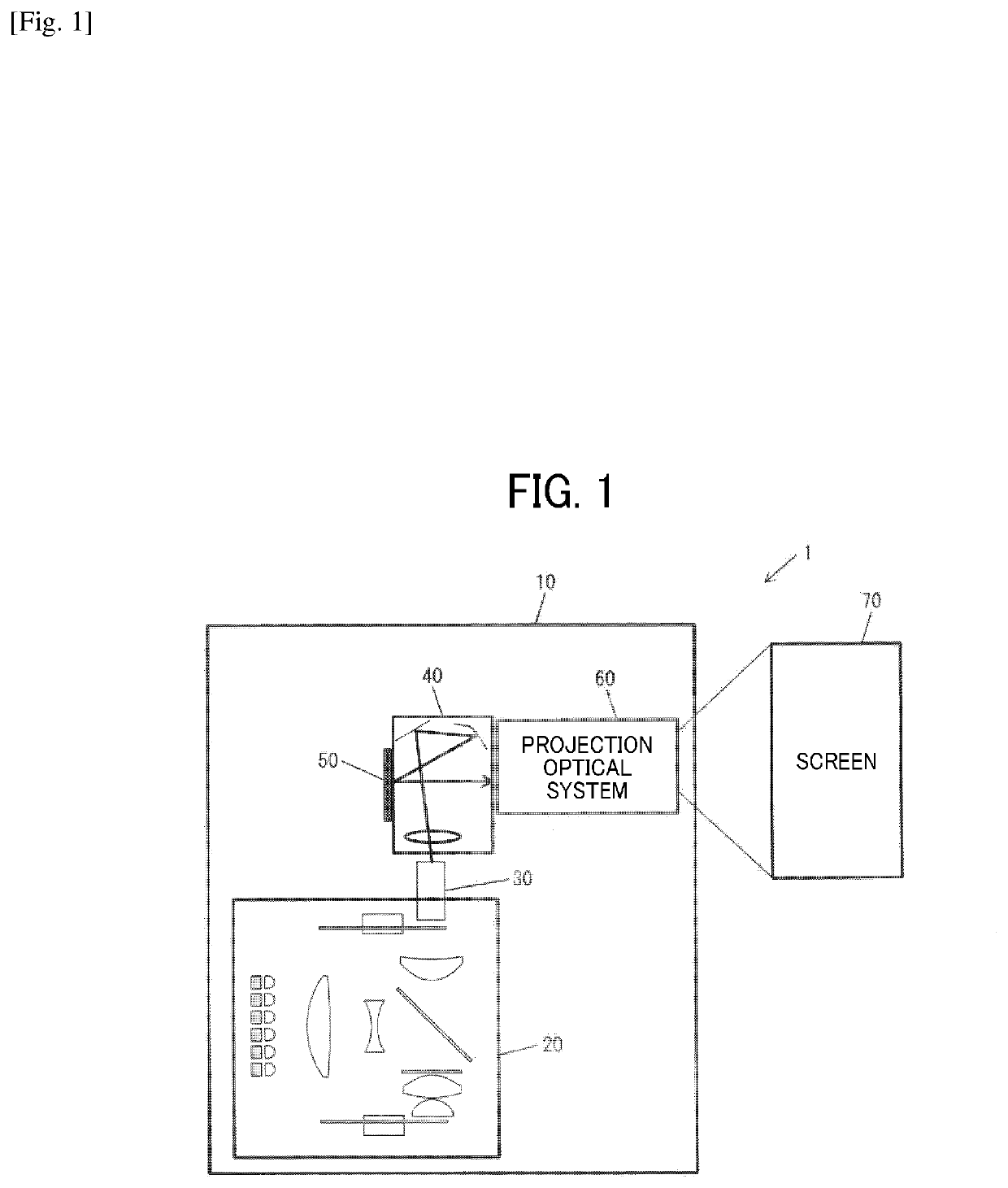
[0048]FIG. 1 schematically illustrates a projector (image projection apparatus) 1 according to a first embodiment.
[0049]The projector 1 includes a housing 10, a light source device 20, a light uniformizing element 30, an illumination optical system 40, an image forming element (image display element) 50, and a projection optical system 60.
[0050]The housing 10 houses the light source device 20, the light uniformizing element 30, the illumination optical system 40, the image forming element 50, and the projection optical system 60.
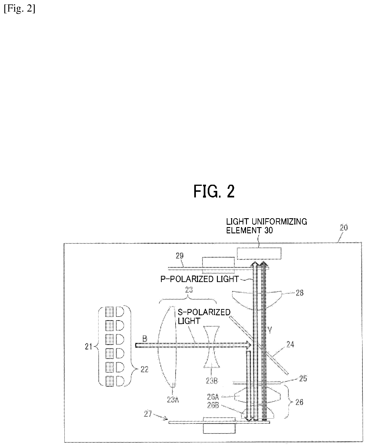
[0051]The light source device 20 emits, for example, light including wavelengths corresponding to colors of RGB. An inner configuration of the light source device 20 is described later in detail.
[0052]The light uniformizing element 30 mixes the light emitted by the light source device 20 to uniformize the light. Examples of the light uniformizing element 30 includes a light tunnel that is a combination of four mirrors, a rod integrator, and a fly eye lens.
[0...
second embodiment
[0105]A projector 1 according to a second embodiment is described below in detail with reference to FIGS. 17 and 18. The same reference sign is applied to a configuration common to that of the first embodiment, and the redundant description is omitted.
[0106]In the second embodiment, the ¼ wave plate 25, which is arranged between the polarization beam splitter 24 and the second optical system 26 of the first embodiment, is omitted, and a collimator lens 80, a ¼ wave plate 81, and a reflecting surface 82 are provided on a side opposite to the second optical system 26 with respect to the fluorescent-body wheel 27. In addition, the fluorescent-body wheel 27 has a configuration different from that of the first embodiment.
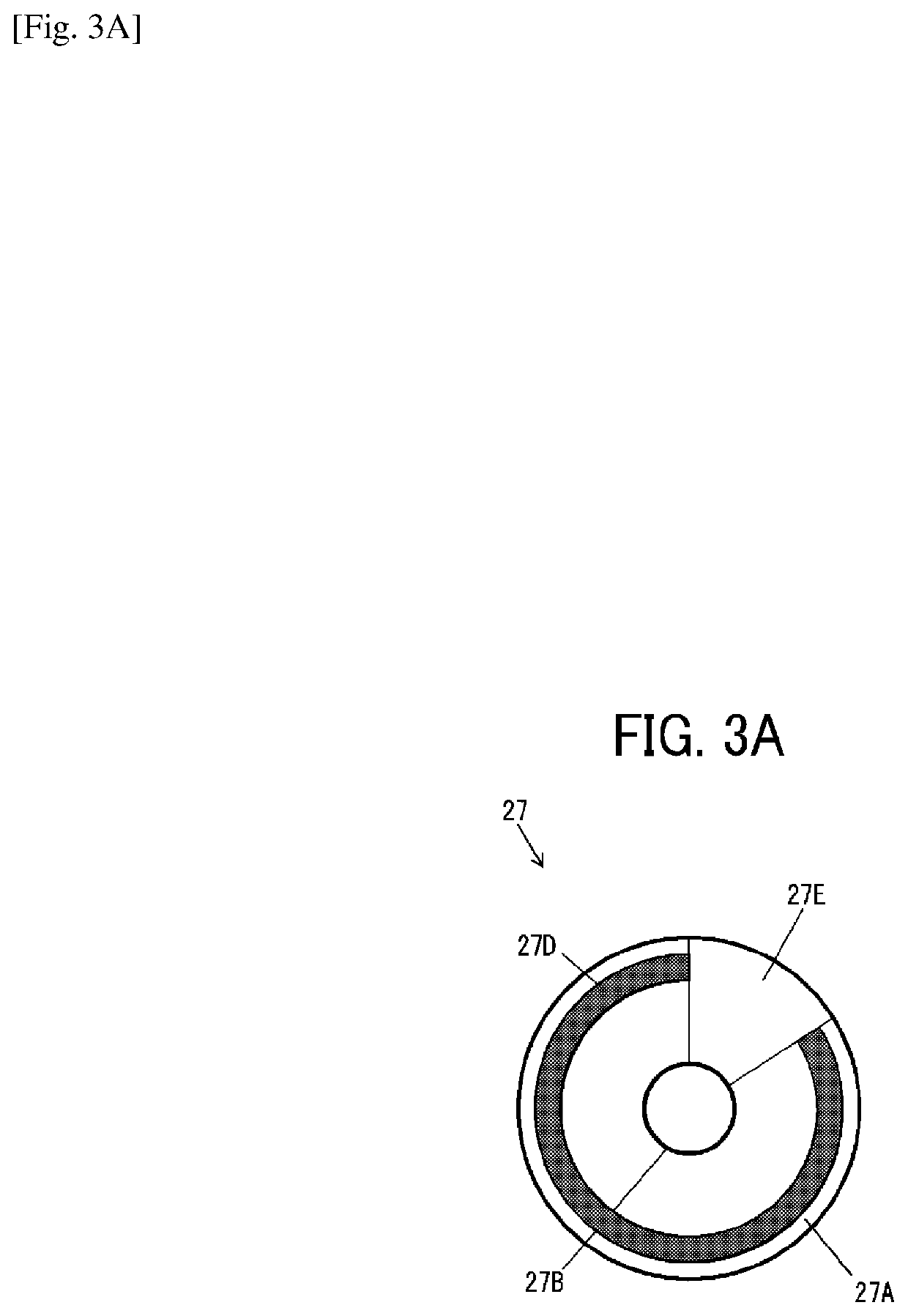
[0107]FIGS. 18A and 18B illustrate a specific structure of the fluorescent-body wheel 27 according to the second embodiment. The fluorescent-body wheel 27 of the second embodiment includes an excitation-light transmissive region 27F instead of the excitation-light reflec...
third embodiment
[0110]A projector 1 according to a third embodiment is described below in detail with reference to FIG. 19. The same reference sign is applied to a configuration common to that of the first embodiment, and the redundant description is omitted.
[0111]The third embodiment differs from the first embodiment for the following points. In particular, the excitation light B emitted by the laser source 21 is P-polarized light, and the polarization beam splitter 24 has a characteristic of transmitting the excitation light B of the P-polarized light guided from the first optical system 23, and reflecting the excitation light B converted into S-polarized light and fluorescence Y from the ¼ wave plate 25, the second optical system 26, and the fluorescent-body wheel 27.
PUM
Abstract
A light source optical system used with an excitation light source configured to emit first color light includes a wavelength conversion unit configured to receive the first color light emitted by the excitation light source and emit second color light with a wavelength different from a wavelength of the first color light, There is a first optical system having a positive power and a second optical system having a positive power provided in this order in an optical path between the excitation light source and the wavelength conversion unit. When a ray parallel to an optical axis of the first optical system is incident on the first optical system, a ray emitted from the first optical system is incident on the second optical system while approaching the optical axis. The second optical system has under-corrected spherical aberration at a paraxial focal position of the second optical system.
Description
TECHNICAL FIELD[0001]The present disclosure relates to a light source optical system, a light source device, and an image projection apparatus.BACKGROUND ART[0002]Projectors (image projection apparatuses) that magnify and project various images are widely used. A projector focuses light emitted by a light source onto a spatial light modulation element, such as a digital micromirror device (DMD) or a liquid crystal display element, and displays, as a color image, light modulated in accordance with an image signal and emitted from the spatial light modulation element onto a screen.[0003]A projector in many cases uses, for example, a high-brightness extra-high-pressure mercury lamp in related art. However, the life of such a lamp is short and the maintenance is frequently required. Owing to this, the number of projectors using, for example, lasers or light emitting diodes (LEDs) instead of extra-high-pressure mercury lamps is growing. This is because a laser and an LED have longer live...
Claims
Application Information
Patent Timeline
Application Date:The date an application was filed.
Publication Date:The date a patent or application was officially published.
First Publication Date:The earliest publication date of a patent with the same application number.
Issue Date:Publication date of the patent grant document.
PCT Entry Date:The Entry date of PCT National Phase.
Estimated Expiry Date:The statutory expiry date of a patent right according to the Patent Law, and it is the longest term of protection that the patent right can achieve without the termination of the patent right due to other reasons(Term extension factor has been taken into account ).
Invalid Date:Actual expiry date is based on effective date or publication date of legal transaction data of invalid patent.

