
Fuse and production method therefor

Active Publication Date: 2021-12-16
AEM COMPONENTS
View PDF0 Cites 0 Cited by
  • Summary
  • Abstract
  • Description
  • Claims
  • Application Information

AI Technical Summary

Benefits of technology

The patent relates to a fuse that has a layer with functions to protect it from electrical arcs and to buffer its performance. This fuse helps to keep other layers stable and provides a solid foundation for them.

Problems solved by technology

With the increase of the rated voltage in the application circuit, the fuse cannot withstand the high-voltage energy during the fusing process, and there are potential safety hazards such as broken, chipped, burned, and flying away from the circuit board, therefore, it is urgent to find a material or structure that can effectively improve the pressure resistance of the fuse.
In one aspect, the disadvantage of this method is that due to that the fuse element penetrates through the pressure relief and heat gathering space, at least one side is located in the groove, and the patent mentions that such a protective element will be sintered, however, a sintering process is a shrinking and densification process for the fuse element and a ceramic substrate; in another aspect, due to that at least one side of the fuse element is in the groove structure, it cannot shrink together with the substrate, which will easily lead to bend and deformation of the fuse element, which will cause the fusion consistency of the fuse element to deteriorate, and it is prone to non-linear fuse that affects the normal operation of the circuit; another disadvantage of this design is that the size of the groove after sintering becomes smaller due to the shrinkage of the ceramic substrate, and the size is difficult to control; in addition, the fusing process of the fuse element will have serious arcing phenomenon under high voltage conditions, especially under the condition that high voltage and high current will be generated when the circuit is short-circuited, and this situation put forward a high requirement to the fuse in view of a breaking capacity, although the design in this patent has a groove for pressure relief, there is no arc extinguishing material that can not strike out the arc, resulting in a strong discharge in the groove, and the unsafe phenomenon of incomplete fusing of the protection element, which causes the circuit board to burn.
This method of dry molding needs to press the two ceramic substrates together in the later stage, and this pressing process will cause the pore-forming agent slurry and the fuse-element to be squeezed, which causes the fuse-element to deform; in another aspect, the porous ceramics or pore-forming agent introduced in this solution will discharge organic matter through low temperature co-firing to form a porous structure, while the existence of these pores will cause the fuse element to diffuse into the above-mentioned pores during the sintering process, which causes defects in the fuse element itself, and results in growth of the resistance of the fuse element and the power consumption in the line, and causes the fusion consistency to become worse, so that abnormal fusing would occur, which affects the normal operation of the circuit.
In the production process, slurry of the arc extinguishing layer is first coated around the fuse element, and then slurry of the buffer layer is printed on the periphery of the arc extinguishing layer and / or the periphery of the fuse element by screen printing; this structure has a certain improvement over the conventional art, but due to both the buffer layer and the arc extinguishing layer have structural weakness and the composition and structure of the two is different, not only the operating procedures are complicated during the low temperature co-firing process, but also the gap between the buffer layer and the arc extinguishing layer will still cause uneven shrinkage of the insulating layer and / or the fuse element permeating into the gap during the low temperature co-firing process, which affects the fusing characteristic of the fuse element.

Method used


Image

  • Fuse and production method therefor
  • Fuse and production method therefor
  • Fuse and production method therefor

Examples


embodiment 1

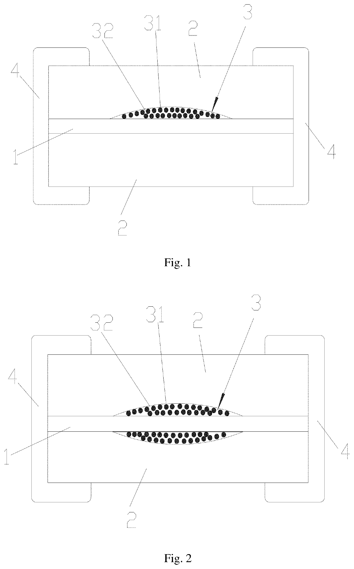
[0054]As shown in FIG. 1, the present disclosure provide a fuse comprising insulating layers 2 and a fuse element 1, the insulating layers comprise an upper insulating layer and a lower insulating layer, the fuse element 1 is arranged between the upper insulating layer and the lower insulating layer, the insulating layers 2 are provided with terminal electrodes 4 electrically connected with the fuse element 1 thereon, and the fuse further comprises a functional layer 3 provided between the fuse element 1 and one of the insulating layers 2, the functional layer 3 comprises a substrate 32 and an arc extinguishing material 31 uniformly or substantially uniformly distributed in the substrate 32, the arc extinguishing material 31 is a glass body and / or ceramic body having sealed cavities, and the substrate 32 comprises low temperature co-fired ceramic powder, aerosol silicon oxide, silicon oxide, inert resin, phosphoric acid and phosphate ester polyester, and the content of the arc extin...

embodiment 2

[0067]As shown in FIG. 2, this embodiment provides a fuse, differing from Embodiment 1 in that the functional layer 3 in the fuse comprises two functional layers 3 arranged above the fuse element 1 and below the fuse element 1, and the functional layer 3 is in contact with the corresponding fuse element 1. The production method for the corresponding fuse is different from the production method of Embodiment 1 in step S5, which is specifically as follows:

[0068]S5, a layer of functional layer slurry layer was printed above the slurry layer of glass-ceramic through steel screen printing, and a layer of fuse element layer slurry having a layer of UV-curable binder was printed above the functional slurry layer using screen printing, wherein the silver content of the fuse element layer slurry was between 55-85%, and a layer of functional layer slurry layer was printed above the fuse element layer slurry through steel screen printing, and a layer of slurry layer of glass-ceramic was coated...

embodiment 3

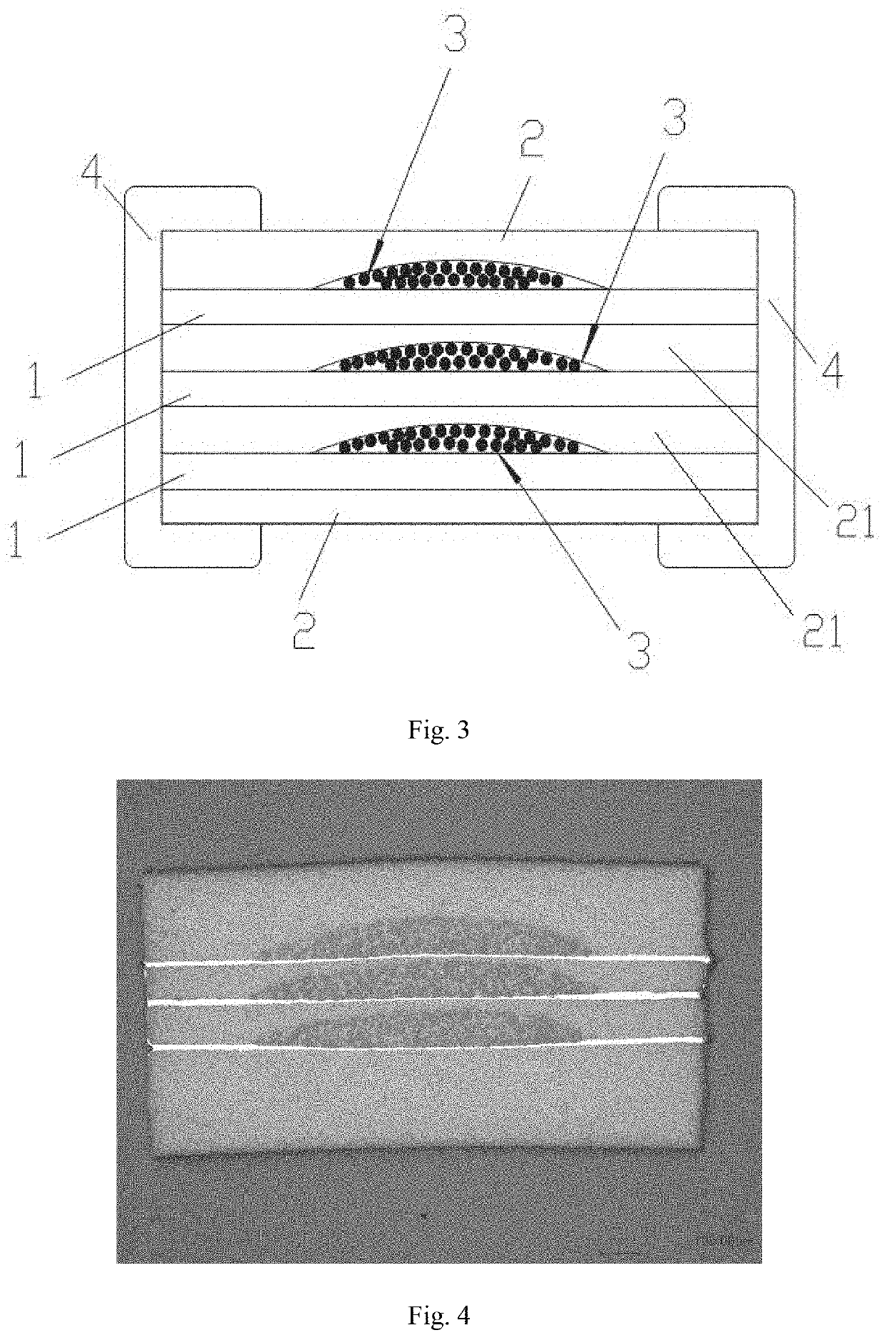
[0069]As shown in FIGS. 3-4, this embodiment provides a fuse, differing from Embodiment 1 in that the fuse element 1 comprises three layers of fuse elements 1 in sequence, a functional layer 3 is provided above each layer of fuse element 1, and the functional layer 3 is in contact with the corresponding fuse element 1, and adjacent fuse elements 1 are separated by insulating materials, namely interlayer 21.

[0070]The production method for a fuse in this embodiment, comprises following steps:

[0071]S1, glass-ceramic slurry was prepared by low temperature co-fired ceramic powder and binder, wherein the solid content in the glass-ceramic slurry was controlled to be 71.43 wt %, and the viscosity was 2.2 kcps after sufficient stirring;

[0072]S2, aerosol silicon oxide, silicon oxide, inert resin, phosphoric acid and phosphate ester polyester were added to the glass-ceramic slurry, and fully stirred and grinded to prepare a pre-slurry of functional layer; the total amount of aerosol silicon o...


PUM


Abstract

A fuse and a production method therefor. The fuse comprises upper and lower insulating layers (2) provided with end electrodes (4), and a fuse body (1) between the upper and lower insulating layers (2). The fuse further comprises a functional layer (3) provided between the fuse body (1) and the insulating layers (2). The functional layer (3) comprises a base material (32) and an arc extinguishing material (31) uniformly or substantially uniformly distributed in the base material (32); the arc extinguishing material (31) comprises a sealed hole; the base material (32) comprises low-temperature co-fired ceramic powder, aerosol silicon oxide, silicon oxide, inert resin, phosphoric acid, and phosphate ester polyester; the content of the arc extinguishing material (31) is 1-50 wt %. The fuse overcomes the shortcomings in the prior art of phenomena such as deformation, bending, and defects occurring to a fuse body (1) caused by the shrinkage mismatch of the fuse body (1) with a buffer layer and an arc extinguishing layer in a sintering process because there is no support, the flatness, consistency and integrity of the fuse body (1) are ensured, and the fuse characteristics and production efficiency are remarkably improved.

Description

CROSS REFERENCE TO RELATED APPLICATIONS[0001]This application is the U.S. National Phase under 35 U.S.C. § 371 of International Application PCT / CN2019 / 111005, filed Oct. 14, 2019, which is hereby incorporated by reference herein in its entirety and which claims the benefit of priority to Chinese Patent Application No. 201811221620.2, filed Oct. 19, 2018.FIELD OF TECHNOLOGY[0002]The present disclosure relates to the field of electrical protection components, and in particular provides a production method for a fuse comprising a functional layer with multiple functions such as arc extinguishing and pressure relief, and a fuse produced by the method.BACKGROUND[0003]Fuse is widely used in overcurrent protection of various electronic components. The metal conductor is used as the fuse-element to be connected in series in the circuit, and when the circuit is abnormal and the current exceeds a specified value, the fuse-element of the fuse will automatically melt to break the circuit and pr...

Claims


Application Information

Patent Timeline
IPC IPC(8): H01H85/18H01H69/02
CPCH01H85/18H01H69/02H01H85/05H01H2085/388H01H85/38H01H85/185H01H85/17
Inventor CHEN, XIQINGLI, XIANGMINGSHAN, XIAOBINGYANG, YONGLIN
Owner AEM COMPONENTS
Features
  • Generate Ideas
  • Intellectual Property
  • Life Sciences
  • Materials
  • Tech Scout
  • Unparalleled Data Quality
  • Higher Quality Content
  • 60% Fewer Hallucinations
Learn More