
Photo-electronic air disinfector

a technology of photoelectronic air and disinfector, which is applied in the direction of disinfection, separation of dispersed particles, and separation of separation processes, etc., can solve the problem of limited practicality of its us

Inactive Publication Date: 2021-12-23
JOHN TECH HLDG LTD
View PDF0 Cites 1 Cited by
  • Summary
  • Abstract
  • Description
  • Claims
  • Application Information

AI Technical Summary

Benefits of technology

The present invention is a photo-electronic air disinfector that can be used in a wider range of environments compared to traditional air purifiers. The device uses UVC light and a photocatalyst to generate strong oxidation power, which can decompose organic matter and various germs in the air and render them harmless. The device has multiple mirrors installed on the internal wall of the air guide unit, which constantly and repeatedly reflect the UVC light to increase the efficacy of sterilization. The air filter first filters out impurities and the photocatalyst module then uses UVC light to deactivate any bacteria or germs that may pass through the filter. The device also generates negative ions that can reduce harmful pollutants in the air. The device is portable, rechargeable, and can be used at a distance from the user.

Problems solved by technology

Photocatalysis is an effective process for use in air and water disinfection, though feasibility of its use has been limited because as a common practice coating of a photocatalyst on the wall or furniture is necessary for it to function for human benefit.

Method used


Image

  • Photo-electronic air disinfector
  • Photo-electronic air disinfector
  • Photo-electronic air disinfector

Examples


Embodiment Construction

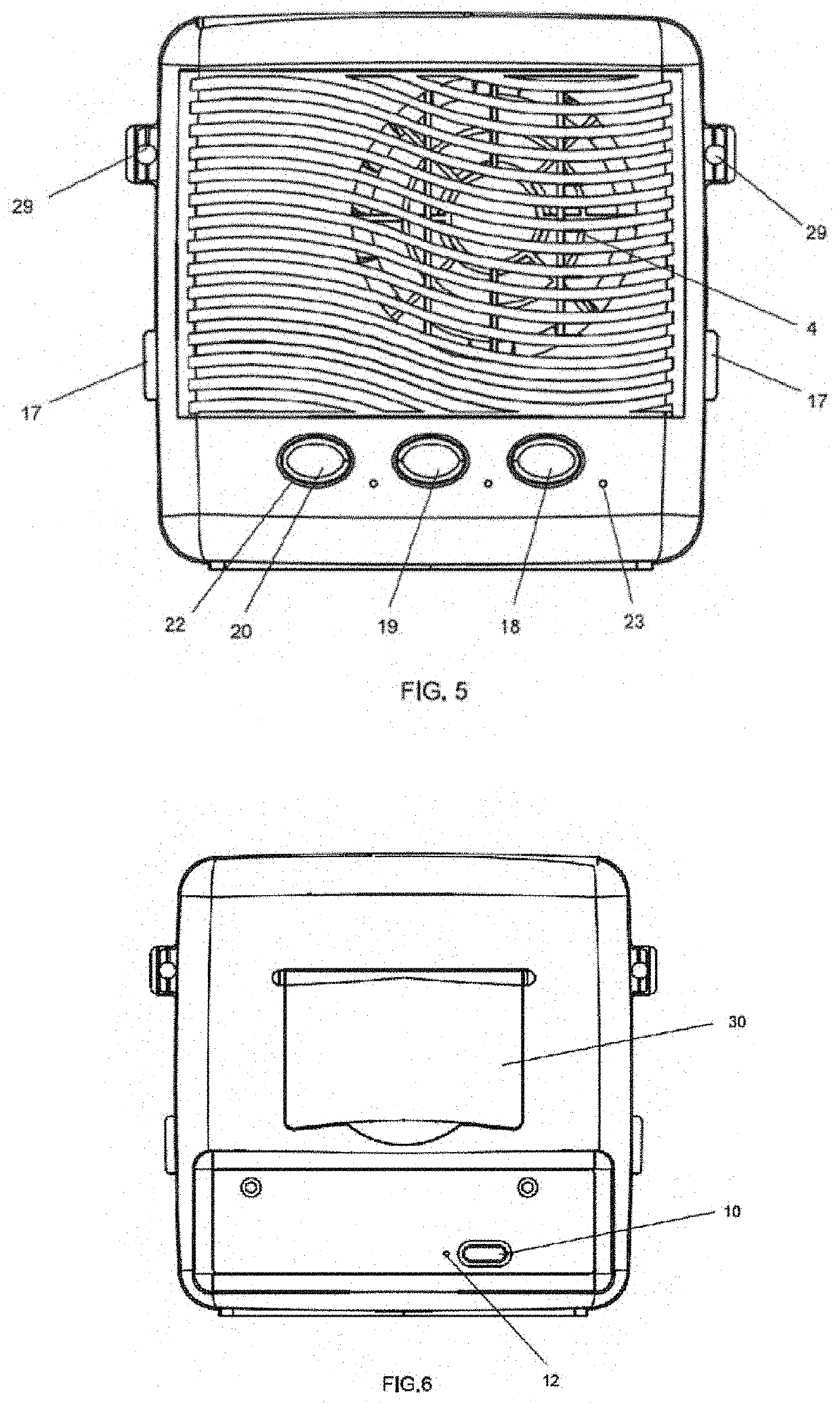
[0027]The photo-electronic air disinfector consists of housing 1, with an air outlet grille 2 located on top of the rear inner housing 3. On the front of the inner housing 25 there is an air inlet grille 4. After ionization, air is expelled via the air outlet grille 2.

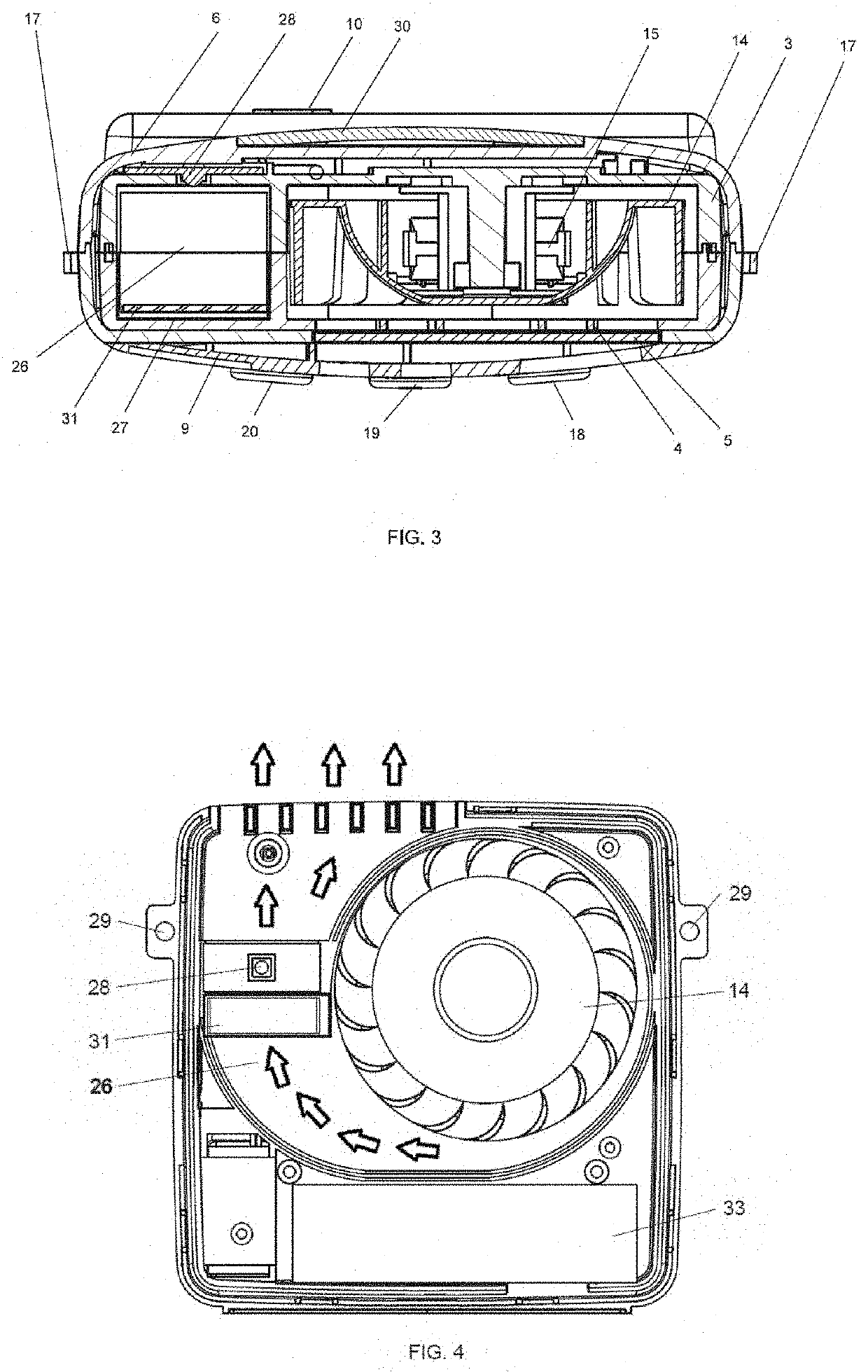
[0028]The detailed structure of the photo-electronic air disinfector is shown in FIG. 2. There is an air inlet grille 4 on the top of the front of the inner housing 25. This air inlet grille 4 provides an air intake. There is an air guide unit 26 connected to the front end of the air inlet grille 4. On the bottom end of the housing 1 there is a control panel cover 7, which secures the electrical function circuit equipment 8. There is a protective cover 9 on top of the front of the housing 1, which secures the replaceable air filter 5. Close to the internal surface of the air inlet grille 4 is the fan 14 and the electric motor 15. The cathodic high-voltage carbonized fiber 16, fixed at the centre of the front surface of...


PUM

PropertyMeasurementUnit
surface areaaaaaaaaaaa
distanceaaaaaaaaaa
voltageaaaaaaaaaa

Abstract

The present invention provides a photo-electronic air disinfector, which comprises a housing containing a fan, a UVC light source, a photocatalyst module consisting of a structure with entire surface area coated with a photocatalyst positioned by the side of the UVC light source, an air guide unit installed with reflecting mirrors on the internal walls of the unit. When air is drawn in the air guide unit of the device, the photocatalyst after absorbing UVC light emitted by the UVC light source or reflected through the mirrors generates superoxide (O2—) and hydroxyl radical (—OH) with strong oxidation power, which can decompose organic matter and various germs in the drawn in air and render them harmless. Sterilization effect of the present invention is four-folded, firstly the air filter removing dusts and germs from the air before entering the device, secondly the photocatalysis produced by the photocatalyst module exposed to direct and reflected UVC light resulting in oxidation process for decomposing organic matter and various germs and rendering them harmless, thirdly UVC light rays and their multiple reflection through the mirrors for bacteria termination, and fourthly negative ions produced and added to the air to condense fine particles into larger ones for settling on the ground and thus reducing harmful pollutants in the air.

Description

CROSS-REFERENCE TO RELATED APPLICATIONS[0001]This application claims priority to Hong Kong Patent Application No. 22020012668.2 filed Jul. 27, 2020, and Hong Kong Patent Application No. 32020009507.5, filed Jun. 17, 2020, the entirety of both of which are incorporated herein by reference.FIELD OF THE INVENTION[0002]This invention relates to a device named the photo-electronic air disinfector employing among others the process of Photocatalysis for air disinfection.BACKGROUND OF THE INVENTION[0003]Photocatalysis is the process when photocatalyst like titanium dioxide coming into contact with light including UV light, an oxidation-reduction reaction occurs such that volatile organic compounds (VOC) and various germs (like mould, E. coli, Staphylococcus aureus and others) are broken down and made harmless. Photocatalysis is an effective process for use in air and water disinfection, though feasibility of its use has been limited because as a common practice coating of a photocatalyst o...

Claims


Application Information

Patent Timeline
Patent Type & Authority Applications(United States)
IPC IPC(8): A61L9/20B01D53/00B01D53/88B01D53/86B01D46/00B03C3/017B03C3/38
CPCA61L9/205B01D2255/802B01D53/885B01D53/8687B01D46/0028B01D46/0032B03C3/0175B03C3/38A61L2209/12A61L2209/14B01D2257/91B01D2257/70B01D2258/06B01D2259/804B01D53/007A61L9/22A61L2209/15
Inventor YUEN, SE KIT
Owner JOHN TECH HLDG LTD
Learn More