
Composite electrode for reducing oxygen

a technology of oxygen oxidation and compound electrode, which is applied in the direction of organic compound/hydride/coordination complex catalyst, physical/chemical process catalyst, cell component, etc., can solve the problem of oxidation deterioration of the other, difficulty in knowing the content of the technology which is required for practical application, and inability to know the effect of which type of catalys

Inactive Publication Date: 2003-05-15
PANASONIC CORP
View PDF3 Cites 43 Cited by
  • Summary
  • Abstract
  • Description
  • Claims
  • Application Information

AI Technical Summary

Benefits of technology

[0006] The present invention solves the problem and provides a composite electrode for reducing oxygen that provides a quasi four-electron reduction at selectivity of nearly 100% for the electrochemical reduction of oxygen without using a catalyst component such as a binuclear metal complex having a central metal atom having a large valency that has a strong oxidation power.
[0007] In order to solve the above-mentioned problems, the composite electrode for reducing oxygen of the present invention includes a composite electrode for reducing oxygen comprising an electrochemical catalyst A that produces hydrogen peroxide by two-electron reduction of oxygen and a catalyst B that decomposes the produced hydrogen peroxide to oxygen, wherein an electrode potential of the composite electrode is set at an oxygen reduction potential of the electrochemical catalyst A, and the oxygen regenerated from the produced hydrogen peroxide by the catalyst B is subjected to the two-electron reduction by the electrochemical catalyst A to produce hydrogen peroxide repeatedly.

Problems solved by technology

However, it is not known which type of catalyst is effective for the one-electron reduction of oxygen, the two-electron reduction or the four-electron reduction at what conditions.
The selectivity of the four-electron reduction differs depending on the complex species, and it is difficult to know the content of a technology which is required for practical application, concerning which type of metal complex is suitable for stably obtaining a higher selectivity to the four-electron reduction.
Such binuclear metal complex has a strong oxidizing power, therefore when it is practically used, there is a problem that it causes the oxidation deterioration of the other constitutional elements such as an electrolyte liquid, an electrode lead, a collector, a battery case, a separator and a gas permeable selective membrane, which are used together with the binuclear metal complex in batteries or cells.

Method used


Image

  • Composite electrode for reducing oxygen
  • Composite electrode for reducing oxygen
  • Composite electrode for reducing oxygen

Examples


example 2

[0070] (3) Preparation of Test Electrodes 21 and 22

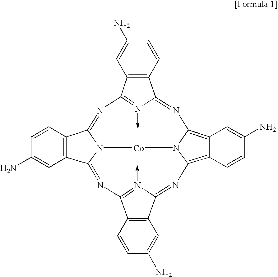
[0071] Test electrodes were prepared in the same manner as in the first example using cobalt-tetraamino phthalocyanine (CoTAPc) as the electrochemical catalyst A and .gamma.-MnOOH (a mixture of Mn.sub.3O.sub.4 and Mn.sub.5O.sub.8) as the catalyst B and using glassy carbon (GC) having a diameter of 6 mm.

[0072] Five (5) .mu.l of a solution in which 1 mM of CoTAPc was dissolved in N,N'-dimethylformamide (DMF) was added dropwise so as to cover the whole exposed face of the GC, and then, the GC was heated by warm wind for 2 hours to obtain the test electrode 22 which had CoTAPc on the GC surface. To 5 .mu.l of an ethanol solution in which 0.05% by weight of Nafion was dissolved, 25 .mu.g of .gamma.-MnOOH powder was dispersed. The resultant solution was added dropwise so as to cover the whole face of the GC having CoTAPc; the GC was heated by warm wind to evaporate ethanol; 5 .mu.l of the same ethanol solution was added dropwise, and etha...

example 3

[0077] (5) Preparation of Test Electrodes 31 and 32

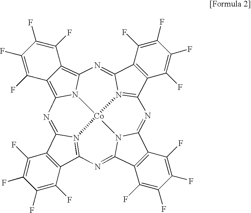
[0078] Test electrodes were prepared in the same manner as in the first example using cobalt-hexadecafluorophthalocyanine (CoHFPc) which has the structural formula indicated in the formula 2 as the electrochemical catalyst A and .gamma.-MnOOH (a mixture of Mn.sub.3O.sub.4 and Mn.sub.5O.sub.8) as the catalyst B and using glassy carbon (GC) having a diameter of 6 mm. 2

[0079] Five (5) .mu.l of a DMF solution in which 1 mM of CoHFPc was dissolved in N,N'-dimethylformamide (DMF) was added dropwise so as to cover the whole exposed face of the GC; the GC was heated by warm wind for 2 hours; further, 5 .mu.l of the same DMF solution was added dropwise; the GC was heated by warm wind for 2 hours to obtain the test electrode 32 which had CoHFPc on the surface.

[0080] Five- (5) .mu.l of a DMF solution in which 50 .mu.g of .gamma.-MnOOH powder was dispersed was added dropwise once so as to cover the whole face of the GC; the GC heated by warm wi...

example 4

[0085] (7) Preparation of Test Electrodes 41 and 42

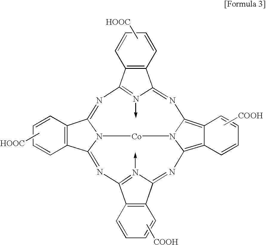
[0086] Test electrodes were prepared in the same manner as in the first example using cobalt-tetracarboxyphthalocyanine (CoCOOHPc) whose structural formula was indicated in the formula 3 as the electrochemical catalyst A and .gamma.-MnOOH (a mixture of Mn.sub.3O.sub.4 and Mn.sub.5O.sub.8) as the catalyst B and using glassy carbon (GC) having a diameter of 6 mm. 3

[0087] Five (5) .mu.l of a DMF solution in which 1 mM of CoCOOHPc was dissolved in N,N'-dimethylformamide (DMF) was added dropwise so as to cover the whole exposed face of the GC; the GC was heated by warm wind for 2 hours; further, 5 .mu.l of the same DMF solution was added dropwise; the GC was heated by warm wind to prepare the test electrode 42 which had CoCOOHPc on the surface.

[0088] Five (5) .mu.l of a solution in which 50 .mu.g of .gamma.-MnOOH powder was dispersed in the afore-mentioned DMF solution containing CoCOOHPc was added dropwise so as to cover the whole face ...


PUM

PropertyMeasurementUnit
reduction potentialaaaaaaaaaa
two-electron reduction potentialaaaaaaaaaa
diameteraaaaaaaaaa

Abstract

A composite electrode for reducing oxygen that provides the quasi four-electron reduction at selectivity of nearly 100% is provided. The composite electrode includes an electrochemical catalyst A that produces hydrogen peroxide by reducing oxygen and a catalyst B that decomposes the produced hydrogen peroxide to oxygen.

Description

[0001] The invention relates to a composite electrode for reducing oxygen in which molecular oxygen is electrochemically reduced. Specifically, the composite electrode for reducing oxygen of the present invention is used for the oxygen electrode or air electrode of an electrochemical device including an air cell such as a zinc-air cell, an aluminum-air cell or a sugar-air cell, and a fuel cell such as an oxygen-hydrogen fuel cell or a methanol fuel cell.DESCRIPTION OF THE RELATED ART[0002] It has been generally known that when oxygen (O.sub.2) is electrochemically reduced, a super oxide is produced at one-electron reduction, hydrogen peroxide is produced at two-electron reduction and water is produced at four-electron reduction (ELECTROCATALYSIS, pp204-205 (1998) edited by JACEK KIPKOWSKI, PHILIP N. ROSS and published by WILEY-VCH Co.). In order to obtain an electrochemical device with a high capacity, high voltage and high current, it is required that the electrochemical reduction ...

Claims


Application Information

Patent Timeline
Patent Type & Authority Applications(United States)
IPC IPC(8): B01J31/00B01J31/18B01J31/22H01M12/06
CPCB01J31/003B01J31/1805Y02E60/523H01M12/06B01J31/2208
Inventor SOTOMURA, TADASHIOHSAKA, TAKEO
Owner PANASONIC CORP
Learn More