Method for controlling a converter

a technology of converters and control methods, applied in the direction of conversion with intermediate conversion to dc, machines/engines, mechanical apparatus, etc., can solve the problems of lack of coordination of switching actions beyond the limit of converter modules, and achieve the effect of better utilization of converters

Active Publication Date: 2021-12-30
WOBBEN PROPERTIES GMBH
View PDF0 Cites 0 Cited by
  • Summary
  • Abstract
  • Description
  • Claims
  • Application Information

AI Technical Summary

Benefits of technology

[0048]The virtual current iv is furthermore used, in particular, to minimize or to optimize downward the required link circuit voltage in the converter. Better utilization of the converter is made possible as a result.

Problems solved by technology

In order to prevent circulating currents within this converter system, measures have to be implemented which at the same time do not qualitatively or quantitatively reduce the power output of the converter system.
What is disadvantageous about previously known methods is the lack of coordination of the switching actions beyond the limit of the converter modules.

Method used


Image

  • Method for controlling a converter
  • Method for controlling a converter
  • Method for controlling a converter

Examples


Embodiment Construction

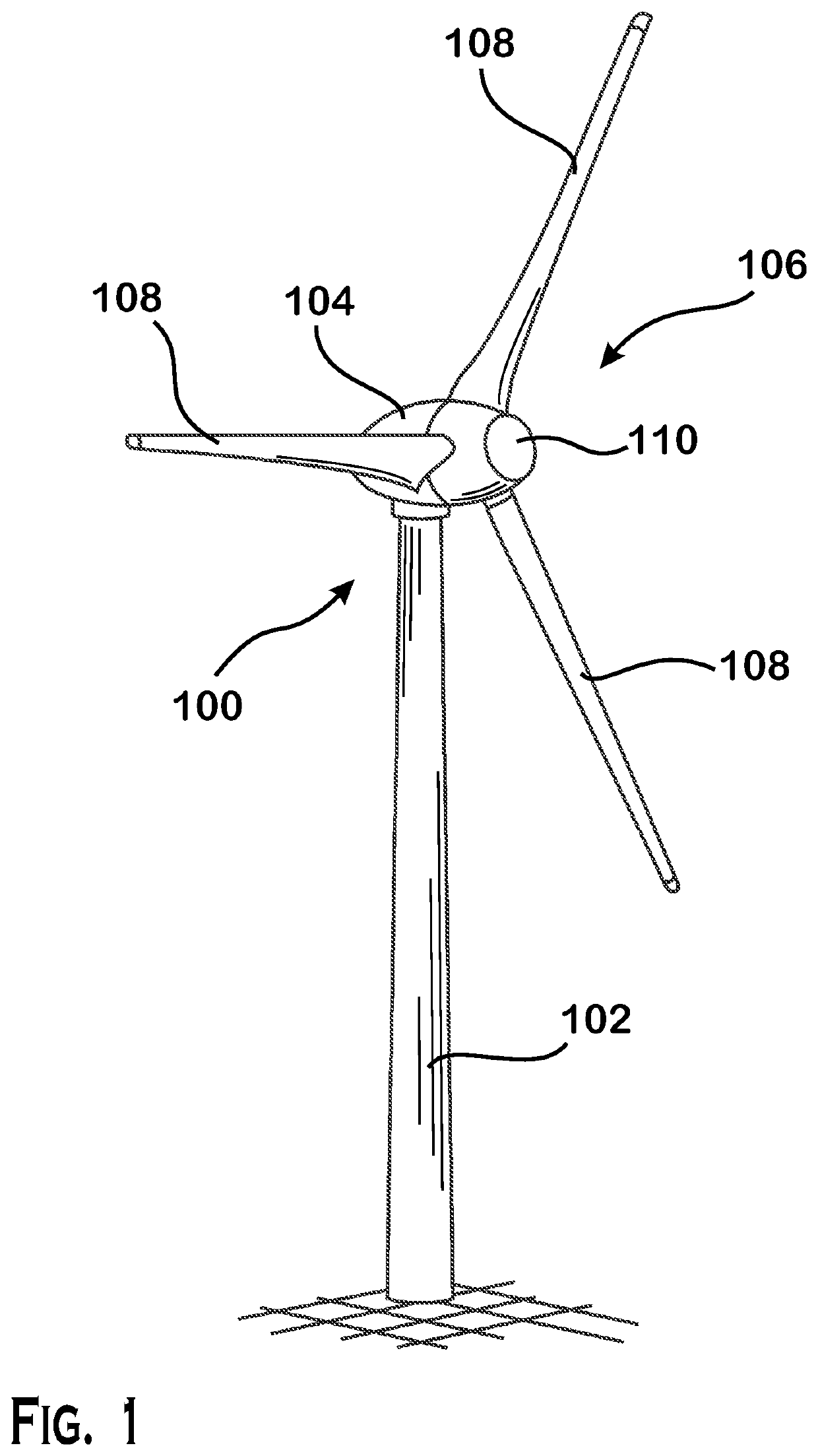
[0068]FIG. 1 shows a perspective view of a wind power installation 100.

[0069]In this respect, the wind power installation 100 has a tower 102 and a nacelle 104. An aerodynamic rotor 106 comprising three rotor blades 108 and a spinner 110 is arranged on the nacelle 104. The rotor 106 is caused to effect a rotational movement by the wind during operation and thereby drives a generator in the nacelle. As a result, the generator generates a current to be fed in, which is fed into an electrical supply network by means of an inverter.

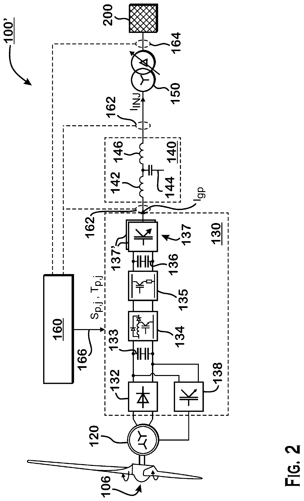
[0070]FIG. 2 shows schematically and by way of example an electrical phase section 100′ of a wind power installation 100, as preferably shown in FIG. 1.

[0071]The aerodynamic rotor of the wind power installation 106 is connected to the generator 120 of the wind power installation. In this case, the generator 120 is preferably embodied as a six-phase ring generator.

[0072]The generator 120 is furthermore connected to an electrical supply network 200, or linked t...


PUM


Abstract

The present disclosure relates to a method for controlling a converter, in particular power converter of a wind power installation. The converter has a plurality of, preferably parallel, converter modules. The method includes the following steps: driving a first converter module, such that the converter module generates a first electrical AC current in a first switch position, driving a second converter module, such that the converter module generates a second electrical AC current in a second switch position, superposing the first electrical AC current and the second electrical AC current to form a total current, detecting the total current of the converter, determining a virtual current depending on the first and second switch positions, and changing the first switch position of the first converter module and/or the second switch position of the second converter module depending on the total current and the virtual current.

Description

BACKGROUNDTechnical Field[0001]The present invention relates to a method for controlling a converter, in particular a power converter of a wind power installation.Description of the Related Art[0002]In the field of generators of electrical energy, in particular in the case of wind power or photovoltaic installations. It is customary for a plurality of converters or converter modules to be connected in parallel in order to increase the total power of the converter system.[0003]In order to prevent circulating currents within this converter system, measures have to be implemented which at the same time do not qualitatively or quantitatively reduce the power output of the converter system.[0004]When controlling converter systems, it is thus necessary to take account of a large number of criteria, such as, e.g., compliance with limit values for the link circuit voltage, potential circulating currents or network-side requirements.[0005]What is disadvantageous about previously known method...

Claims


Application Information

Patent Timeline
Patent Type & Authority Applications(United States)
IPC IPC(8): H02M7/493H02J3/38H02M1/00F03D9/25
CPCH02M7/493H02J3/381F05B2220/706F03D9/25H02J2300/28H02M1/0009H02M7/5395H02M7/53871H02M7/53873H02M1/325Y02E10/72Y02E10/76H02M5/42H02M5/44H02M5/4585
Inventor GENSIOR, ALBRECHT
Owner WOBBEN PROPERTIES GMBH
Why Eureka
Try Eureka