Eureka AIR delivers breakthrough ideas for toughest innovation challenges, trusted by R&D personnel around the world.

Ship comprising a system for reducing the vibrations originating from the casing and method for building said ship

Pending Publication Date: 2022-01-06
FINCANTIERI
View PDF2 Cites 0 Cited by
  • Summary
  • Abstract
  • Description
  • Claims
  • Application Information

AI Technical Summary

Benefits of technology

The invention is a system that reduces vibrations and noise from the engine of a ship. This system aims to prevent the transmission of these vibrations through the structure of the ship without the need for buffer spaces. The system is simple in design and production, with similar costs to traditional solutions.

Problems solved by technology

The tube bundle constitutes a real barrier to the flow of the gases that is necessary for exchanging heat but generates vibrations and noise.
Consequently, energy is transferred to the support structure by means of the bases of the exhaust gas boiler in the form of significant structural noise.
However, the scrubbers have a significant influence on the stability of the ship since they are positioned in the highest part of the casing and are significantly heavier than a simple pipeline.
As already pointed out, several of the components arranged inside a casing transfer noise and vibrations to said casing and therefore to the structures surrounding it.
In particular, the components of the exhaust flues transmit low-frequency vibrations generated by the internal combustion engines of the ship to the casing.
In several cases, the use of elastic suspensions does, however, not make it possible to satisfactorily reduce the vibrations, at least in the vicinity of the casing.
In particular, these elastic suspensions are not able to cut low-frequency vibrations.
The arrangement of said buffer spaces is not, however, an entirely satisfactory solution, since, as well as not always ensuring effective cutting of the vibrations, it takes away useful space in valuable zones of the ship.

Method used


Image

  • Ship comprising a system for reducing the vibrations originating from the casing and method for building said ship
  • Ship comprising a system for reducing the vibrations originating from the casing and method for building said ship
  • Ship comprising a system for reducing the vibrations originating from the casing and method for building said ship

Examples


Embodiment Construction

[0038]The subject of this invention is a ship with a system for reducing the vibrations originating from the casing and a method for building said ship.

[0039]In particular, the ship that is the subject of this invention may be a cruise ship.

[0040]With reference to the attached drawings, reference numeral 1 indicates, as a whole, a ship according to the invention.

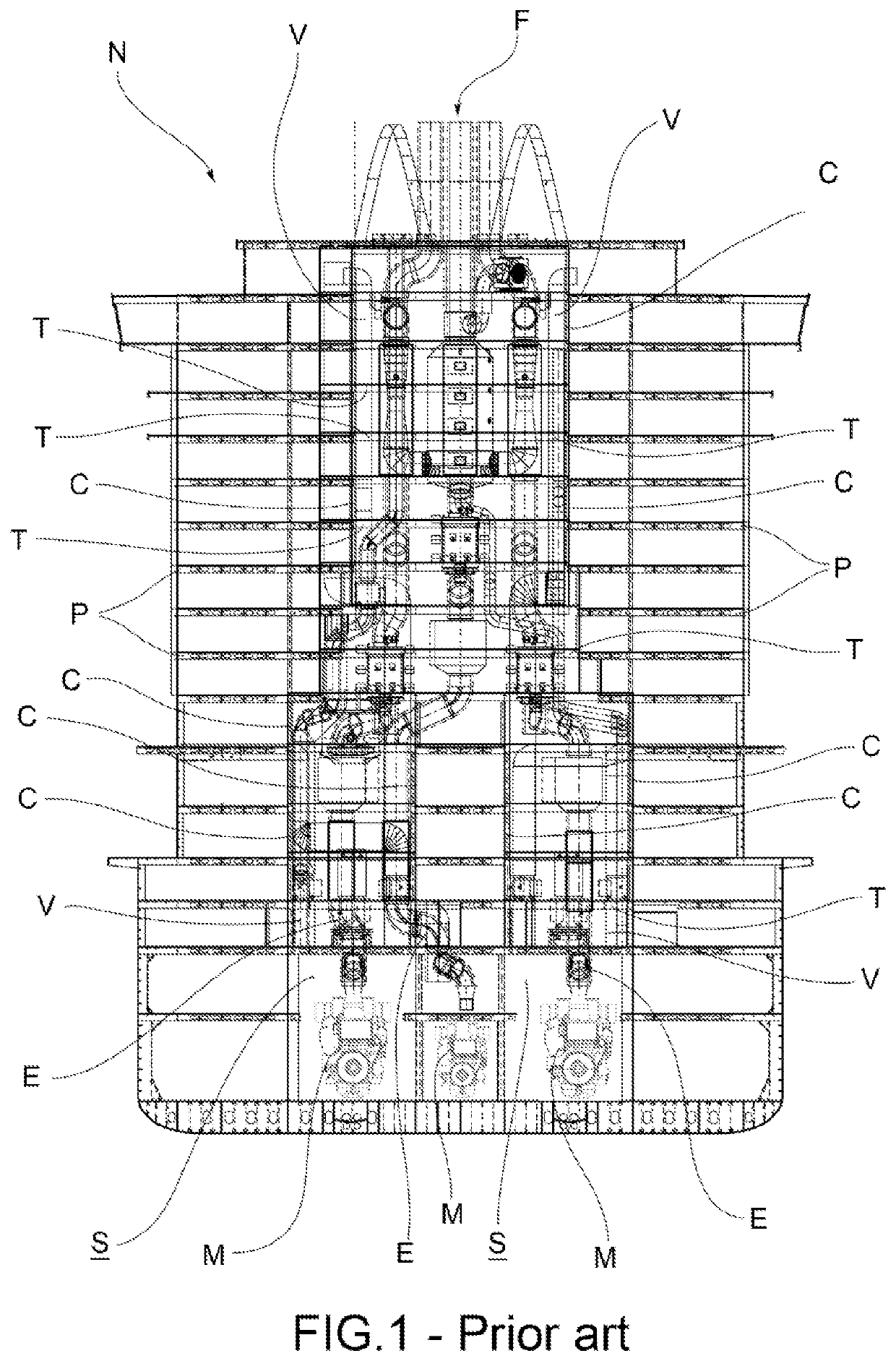
[0041]In accordance with a general embodiment of the invention shown in FIG. 4, the ship 1 comprises:[0042]a hull 2;[0043]a plurality of decks 10 arranged inside the hull 2;[0044]at least one engine casing 20 that delimits a cavity 21 extending vertically across the abovementioned plurality of decks 10 from an engine room 22 up to a funnel 23; and[0045]at least one exhaust flue 30 for the fumes generated by one or more internal combustion engines 24 arranged in the abovementioned engine room 22.

[0046]In particular, the abovementioned internal combustion engines 24 may be diesel engines or diesel / gas engines.

[0047]The aboveme...


PUM

PropertyMeasurementUnit
Fractionaaaaaaaaaa
Fractionaaaaaaaaaa
Fractionaaaaaaaaaa

Abstract

The invention relates to a ship, comprising: at least one casing that delimits a cavity extending vertically across the ship's decks; at least one exhaust flue that is installed inside said casing and comprises a plurality of concentrated mass components and a plurality of components with mass distributed in length; a plurality of structures that support the plurality of said components inside the casing. Said support structures comprise: a plurality of main platforms, which define a main support base inside said cavity and is connected to walls of the casing at a ship deck by means of the interposition of main elastic suspensions; and a plurality of secondary platforms, which are directly or indirectly supported only by one of said main platforms and defines a secondary support base arranged at a different height with respect to the main support base that is defined by the corresponding main platform.

Description

CROSS-REFERENCE TO RELATED APPLICATION[0001]This application claims priority to Italian Patent Application No. 102020000016102 filed on Jul. 3, 2020, the entire contents of which is hereby incorporated in its entirety by referenceFIELD OF APPLICATION[0002]The subject of this invention is a ship comprising a system for reducing the vibrations originating from the casing and a method for building said ship.[0003]In particular, the ship that is the subject of this invention is a cruise ship.BACKGROUND[0004]The exhaust flues E for the combustion fumes generated by the engines M of a ship N are arranged inside one or more vertical cavities that extend from the engine room S to the funnels F, passing through all of the ship's decks P, as illustrated in FIG. 1. Each of these cavities, which usually have a rectangular cross section, is delimited around the edge thereof by a closed structure C, which is suitable to separate said cavity from the rest of the ship. This closed structure C, the ...

Claims


Application Information

Patent Timeline
IPC IPC(8): B63H21/34B63H21/30
CPCB63H21/34B63B3/02B63H21/305B63H21/32B63H21/30B63B73/00B63B17/0081B63B2035/004F01N13/004F01N13/1811F01N13/0097F01N3/2066F01N3/04F01N1/00F01N13/08F01N2530/22Y02T10/12B63H21/36B63B73/20F16F15/04
Inventor PUGNETTI, ROBERTA
Owner FINCANTIERI
Why Eureka
Eureka Blog
Learn More