
Infrastructure system

a technology of infrastructure system and path, applied in the direction of vehicle position/course/altitude control, process and machine control, instruments, etc., can solve the problem of vehicles hitting objects in the travel path, and achieve the effect of reducing the distan

Pending Publication Date: 2022-01-06
IMA SCHELLING DEUT GMBH
View PDF0 Cites 0 Cited by
  • Summary
  • Abstract
  • Description
  • Claims
  • Application Information

AI Technical Summary

Benefits of technology

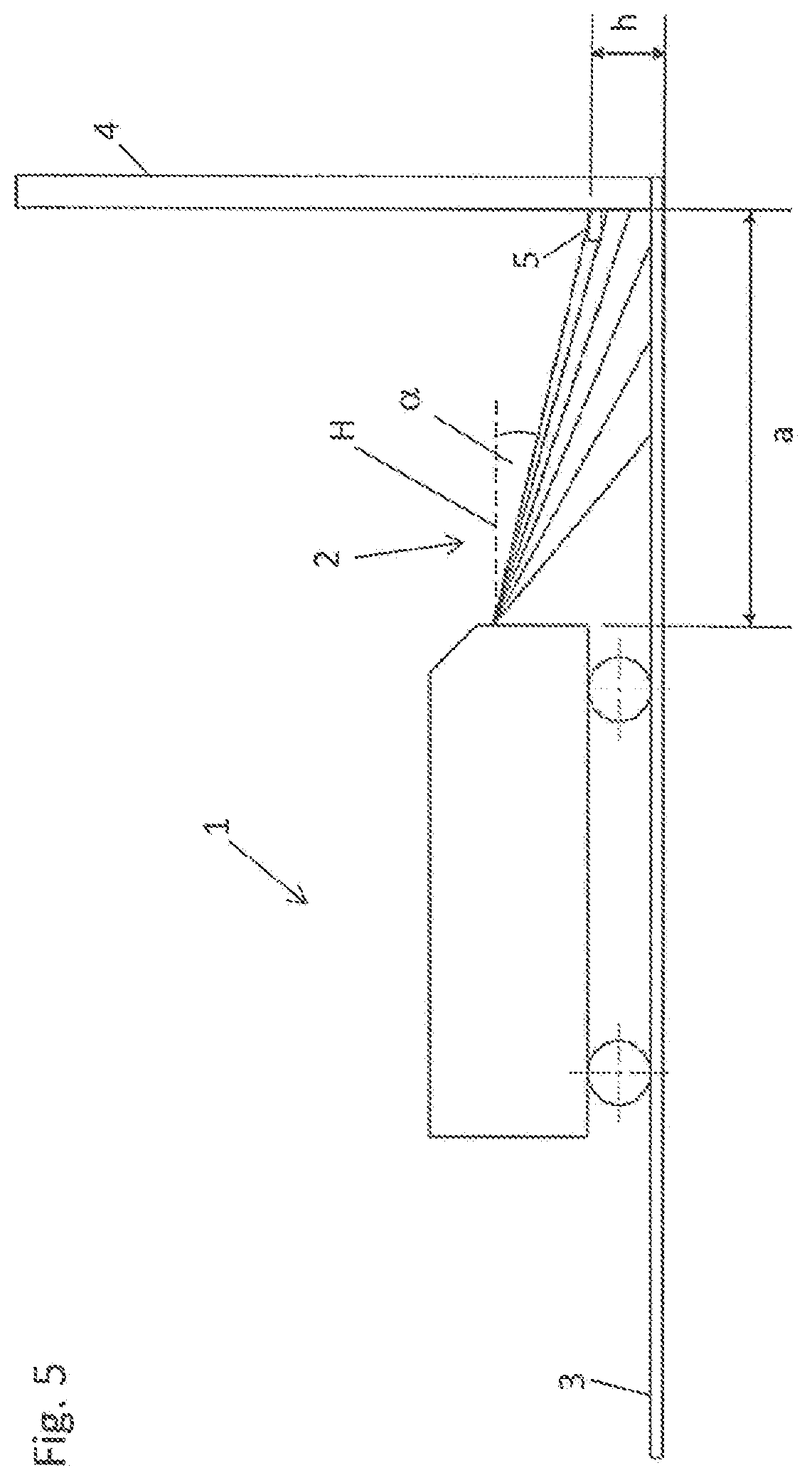
The patent describes a system for controlling the movement of automated guided vehicles in a safety region. The system uses sensors to detect the approach of the vehicle and opens a door or gate to allow the vehicle to pass through without stopping. The system can also set a minimum distance between the vehicle and the safety region based on the sensor's height and beam angle, to ensure the vehicle doesn't exceed the allowed distance. The technical effect of this invention is to improve safety in the workplace by controlling the movement of automated guided vehicles and preventing accidents.

Problems solved by technology

As corresponding automated guided vehicles drive through the infrastructure, there is always a chance that these vehicles might hit objects in the travel path or, for example, obstacles might appear.

Method used


Image

  • Infrastructure system
  • Infrastructure system

Examples


Embodiment Construction

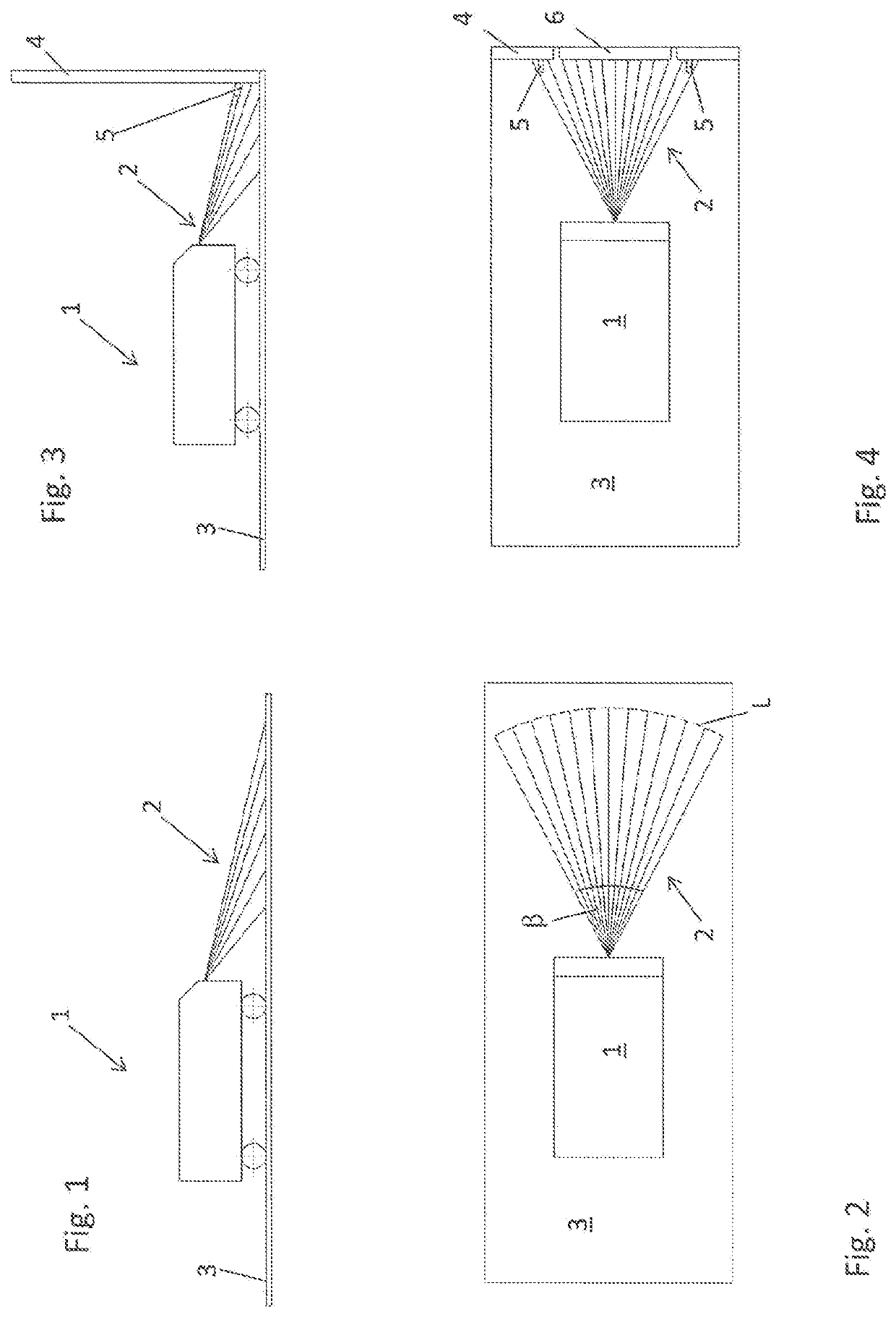
[0029]FIG. 1 is a schematic view of an AGV 1 which moves automatically on a floor 3. The AGV 1 is part of an automated guided vehicle system, which in turn is part of an infrastructure system, and has a suitable navigation device (not shown). In addition, the AGV 1 has a safety scanner that emits a scanning signal 2 into the region in front of the AGV. FIG. 2 shows that the scanning signal 2, which can be a laser beam or any other type of reflectable signal, is preferably emitted by the safety scanner into the space in front of the AGV 1 at an aperture angle β. If the scanning signal is a laser beam, for example, this beam is periodically moved back and forth as indicated by the line L. In so doing, the scanning signal 2 travels over a certain angle β in the space at a particular scanning frequency (this can be, for example, the number of back and forth movements of the scanning signal per unit of time). Objects that lie within the cone thus formed by the scanning beam reflect the s...


PUM


Abstract

An infrastructure system with an automated guided vehicle system (FTS) that has an automated guided vehicle (AGV), and a control means. The infrastructure system has a safety region that has an entrance region through which the AGV can drive, wherein the AGV has a safety scanner which emits a scanning signal. The safety scanner is designed to detect objects and obstacles located in the driving region of the AGV independently of a navigation system for controlling and determining the position of the AGV. A sensor is arranged in the entrance region, which sensor can detect the scanning signal emitted by the AGV. The control means is designed, in response to a predefined scanning signal detected by the sensor, to determine the presence and / or authorization of the AGV in the entrance region, which authorization is required for driving into the safety region.

Description

CROSS REFERENCE TO RELATED APPLICATIONS[0001]This patent application is the US national phase of and claims priority on and the benefit of International Application No. PCT / EP2019 / 083161 having an international filing date of 29 Nov. 2019, which claims priority on and the benefit of German Patent Application No. 10 2018 130 720.9 having a filing date of 3 Dec. 2018.BACKGROUND OF THE INVENTIONTechnical Field[0002]The invention relates to an infrastructure system, comprising an automated guided vehicle system (FTS) that has at least one automated guided vehicle, and a control means, wherein the infrastructure system also comprises at least one safety region that has an entrance region through which the automated guided vehicle can drive.Prior Art[0003]Infrastructure systems and methods for operating such infrastructure systems are known, for example, from DE 20 2015 001 193 A1, DE 20 2013 008 609 U1 and DE 697 12 906 T2. Automated guided vehicle systems are often used for automation i...

Claims


Application Information

Patent Timeline
IPC IPC(8): G05D1/02
CPCG05D1/024G05D2201/0216G05D1/0214
Inventor RISCHE, STEFAN
Owner IMA SCHELLING DEUT GMBH
Learn More