
Dual inline memory module heat sink for conduction cooled environments

a memory module and heat sink technology, applied in the computer field, can solve the problems of increasing the need for server platforms, and achieve the effect of reducing failure occasions and highly reliable methods of transfer

Pending Publication Date: 2022-01-06
CRYSTAL GROUP
View PDF6 Cites 0 Cited by
  • Summary
  • Abstract
  • Description
  • Claims
  • Application Information

AI Technical Summary

Benefits of technology

The present invention is a system for cooling memory chips in DIMMS to prevent failure. The system includes a clam-like heat exchange structure, a heat pipe, and highly reliable methods for transferring heat from the memory chips to discrete areas inside an enclosed computer platform. The invention aims to achieve efficient cooling without causing failures associated with cooling fans and pumps. The technical effects of the invention include reduced failure occasion, improved reliability, and better cooling performance.

Problems solved by technology

However, these server platforms are becoming more necessary because of the need for virtualization and compute density in smaller spaces.
One of several obstacles requiring resolution is the need to enclose the computer platform while simultaneously reducing moving parts, such as cooling fans and pumps on these computer platforms.

Method used


Image

  • Dual inline memory module heat sink for conduction cooled environments
  • Dual inline memory module heat sink for conduction cooled environments
  • Dual inline memory module heat sink for conduction cooled environments

Examples


Embodiment Construction

[0034]Though this description details are given of a motherboard, DIMM and a DIMM connector, it should be understood that different circuit cards with different types of electronic components could be used with different connector sizes and configurations. It is intended that these specific details not limit the scope of the present invention, unless repeated in the claims, but instead fully enable a specific and / or best mode of the invention and other variations of this card and connector types are intended to be readily understood from the following description and included within the scope and spirit of the present invention.

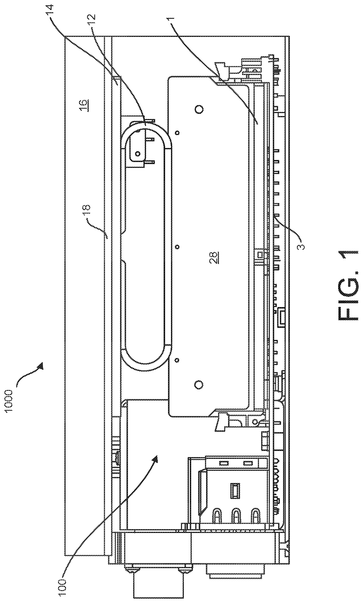
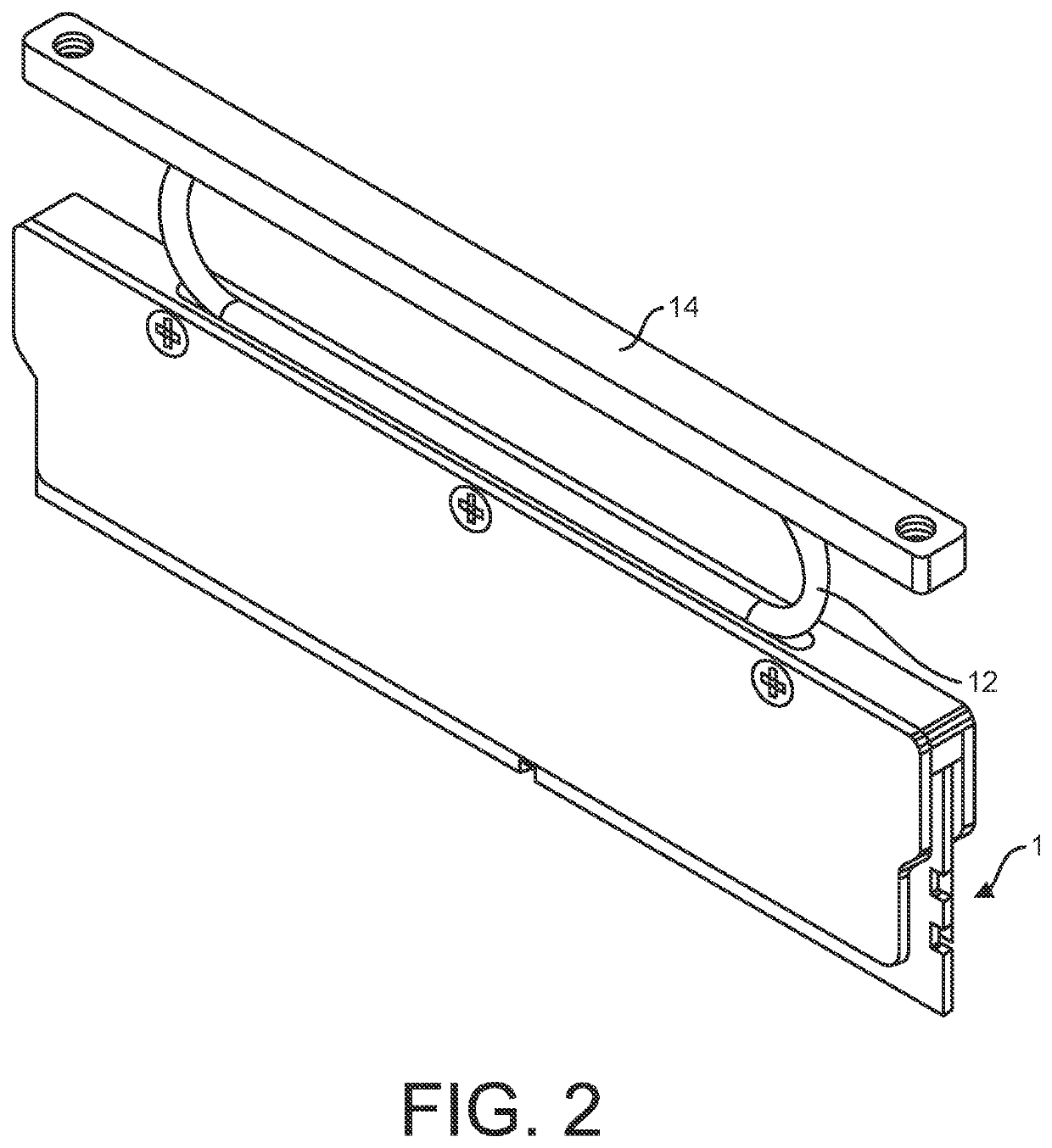
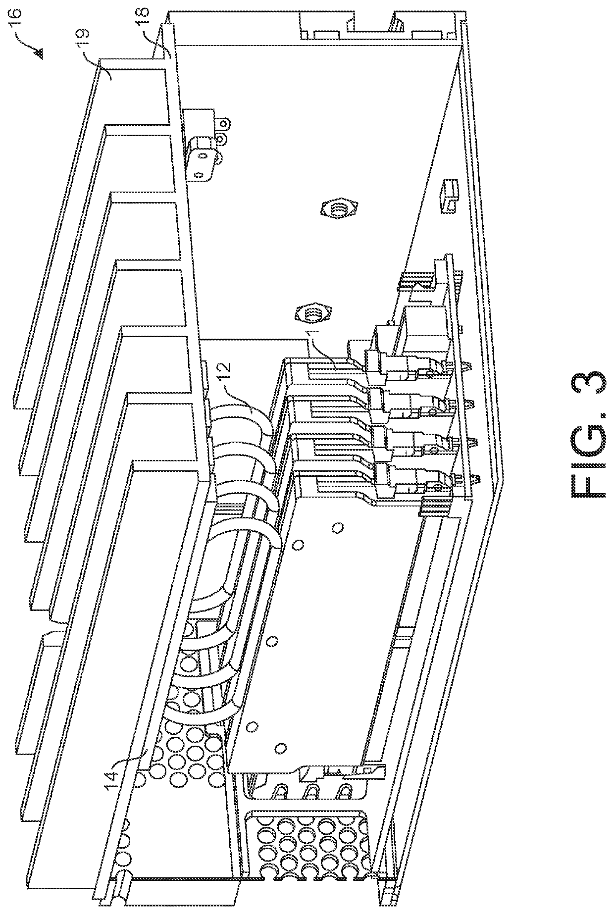
[0035]Now referring to the drawings wherein like numerals refer to like matter throughout, and more specifically referring to FIG. 1, there is shown a DIMM cooling system 100, of the present invention which is inside an enclosed high density computer platform 1000. The system 100 includes a DIMM 1 or other secondary circuit board in a perpendicular orientatio...


PUM


Abstract

A system and method enabling the use of convection cooled dual-inline memory modules (DIMM) in non-convection environments, specifically used for computing applications for harsh environments. This system and method describes a design which transfers heat from the various components on the memory module to thermally opportunistic areas of an enclosure in the absence of sufficient or in some cases any convective cooling conditions. The system and method describes a sandwiched metal heat plate assembly, being constructed from a thermally conductive material, which is attached to a heat pipe, designed to be highly thermally conductive, which is further attached to a thermally conductive cold plate saddle, which in turn is connected to a thermal sink. The heat generated in the DIMM is conducted to the heat plate by way of a thermal interface material, this energy transferred to the heat pipe, and then to a cold plate which dissipates the energy to the ambient environment. The system does not require a plurality of fins inside the enclosure, liquid cooling, nor airflow within the enclosure to accomplish the memory thermal management. The invention includes a heat pipe saddle, a heat pipe, a clamshell heat extraction mechanism in conjunction with a thermal interface compound for improving the heat transfer from the DIMM to the heat sink.

Description

CROSS REFERENCE TO RELATED APPLICATIONS[0001]This application claims the benefit of the filing date of the provisional patent application having Ser. No. 63 / 048,625 filed Jul. 6, 2020, the contents of which is incorporated herein in its entirety by this reference.FIELD OF THE INVENTION[0002]The present invention relates to computers and more particularly, dual inline memory modules (DIMMs) and systems and methods for cooling the same.BACKGROUND OF THE INVENTION[0003]Server class computer platforms were typically not employed in environments that are harsh, such as military vehicles, construction vehicles, weapons platforms, space launch systems, etc. However, these server platforms are becoming more necessary because of the need for virtualization and compute density in smaller spaces. One of several obstacles requiring resolution is the need to enclose the computer platform while simultaneously reducing moving parts, such as cooling fans and pumps on these computer platforms. In mo...

Claims


Application Information

Patent Timeline
Patent Type & Authority Applications(United States)
IPC IPC(8): H05K7/20F28D15/02F28D15/04
CPCH05K7/20336F28D15/046F28D15/0233H05K7/20509F28D15/0275H05K7/20445
Inventor SHAW, JAMES E.JOHNSON, ROBERT
Owner CRYSTAL GROUP
Learn More