Blower with silencer

a technology of silencer and blower, which is applied in the direction of liquid fuel engines, instruments, machines/engines, etc., can solve the problems of increasing the size of the entire device in which the fan and the silencer are installed, and achieve the effect of reducing the siz

Pending Publication Date: 2022-01-13
FUJIFILM CORP
View PDF0 Cites 0 Cited by
  • Summary
  • Abstract
  • Description
  • Claims
  • Application Information

AI Technical Summary

Benefits of technology

[0023]According to the present invention, it is possible to provide the blower with a silencer that can sile

Problems solved by technology

As disclosed in WO2004/061817, in a case in which the silencer is installed on an outer peripheral portion of the passage of wind generated by the fan in order to ensure the ventilation property

Method used


Image

  • Blower with silencer
  • Blower with silencer
  • Blower with silencer

Examples


example 1

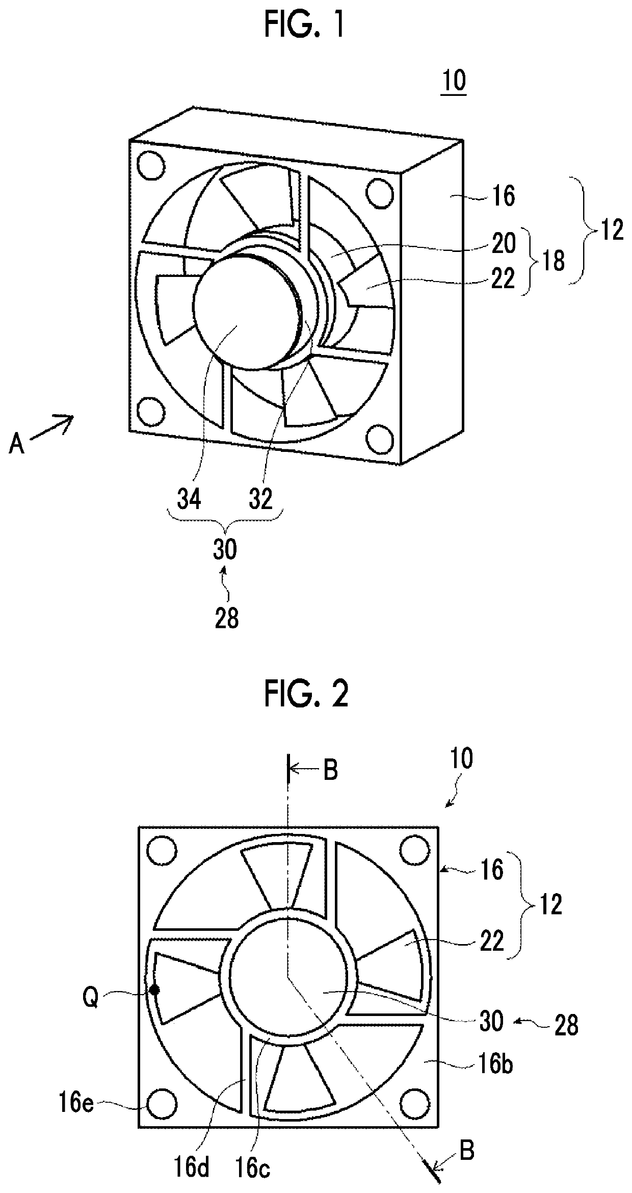
[0213]San Ace 60 (Model: 9GA0612G9001 manufactured by SANYO DENKI CO., LTD.) was used as the axial fan 12. This axial fan has an outer diameter of 60 mm×60 mm and a thickness of 10 mm, a shaft portion having a diameter of 31 mm, and a rotor having an outer diameter (diameter of rotation region) of 56 mm.

[0214]A configuration was adopted in which the silencer includes one Helmholtz resonator 40.

[0215]FIG. 29 is a schematic cross-sectional view of the Helmholtz resonator 40.

[0216]As shown in FIG. 29, a configuration was adopted in which the Helmholtz resonator 40 has an outer diameter of a columnar shape with a diameter of 31 mm and a thickness of 15 mm, an inner space of a columnar shape with a diameter of 26 mm and a thickness of 10 mm, and a through-hole with a diameter of 4.5 mm and a length of 3 mm formed in a center portion of one bottom surface. The Helmholtz resonator 40 was formed by using an acrylic plate.

[0217]The Helmholtz resonator 40 was attached to the cover portion of ...

example 1-2

[0242]Next, in Example 1, a result of a study conducted by changing the length of the duct DU (hereinafter referred to as a duct length) will be described.

[0243]In cases in which the length of the duct DU was 0 cm (that is, without a duct), 3 cm, and 18 cm, the sound pressure intensity was measured in the same manner as described above and the silencing volume was obtained.

[0244]The results are shown in FIG. 33. In addition, FIG. 34 is a graph showing a relationship between the silencing volume and the duct length at 1225 Hz.

[0245]From FIGS. 33 and 34, it was found that the silencing effect of 1.5 dB or more could be obtained regardless of the presence or absence of the duct. In addition, it was found that the silencing volume is increased in a case in which the duct length is 5 cm or more.

example 1-3

[0246]Next, a result of a study conducted by changing only the outer diameter of the silencer (Helmholtz resonator) in Example 1 will be described. Specifically, by changing the outer diameter of the silencer, an area ratio of the region in which the blade region and the silencer overlap with each other to the blade region was changed, and the effect was studied.

[0247]In a case of Example 1, since the diameter of the shaft portion and the diameter of the silencer are the same, the area ratio (hereinafter, also referred to as a shielded area) of the region in which the blade region and the silencer overlap with each other to the blade region was 0%.

[0248]The outer diameter of the silencer was changed to produce the shielded area 7.4%, 24.2%, and 58.3%, respectively, and the air volume was measured in the same manner as in the above. Note that the duct length was 6 cm.

[0249]The results are shown in FIG. 35.

[0250]From FIG. 35, it was found that the air volume was reduced as the shielde...


PUM


Abstract

A blower with a silencer has the blower including an axial fan including a casing, a motor attached to the casing, and a rotor having a shaft portion attached to the motor and rotated and a blade formed to protrude to an outer side of the shaft portion in a radial direction, and a silencer attached to the casing, in which the silencer includes a resonator that selectively silences a dominant sound generated by the axial fan, the silencer is disposed at a position in which at least a part of the silencer overlaps with the shaft portion, as viewed from a rotation axis direction of the rotor, and in a case in which, in a cross section perpendicular to a rotation axis of the rotor, a circle around the rotation axis, which has a radius of a line connecting the rotation axis and a point of a most distal end of the blade, is defined as a rotation region, an area of the silencer in the cross section perpendicular to the rotation axis is smaller than an area of the rotation region.

Description

CROSS-REFERENCE TO RELATED APPLICATIONS[0001]This application is a Continuation of PCT International Application No. PCT / JP2020 / 012600 filed on Mar. 23, 2020, which claims priority under 35 U.S.C § 119(a) to Japanese Patent Application No. 2019-082630 filed on Apr. 24, 2019. Each of the above application(s) is hereby expressly incorporated by reference, in its entirety, into the present application.BACKGROUND OF THE INVENTION1. Field of the Invention[0002]The present invention relates to a blower with a silencer.2. Description of the Related Art[0003]In an information device, such as a personal computer (PC), a duplicator, and the like, in order to cool an inside of the device, a fan is used to exhaust heated air in the device.[0004]Out of a noise generated from such a cooling fan, a noise of which a frequency is determined by the number of blades and a rotation speed thereof has a high sound pressure at a specific frequency and a very strong pure tone (tone) component, which is jar...

Claims


Application Information

Patent Timeline
IPC IPC(8): F04D29/66H02K7/00H02K7/14H02K5/04F04D19/00F04D29/52
CPCF04D29/665H02K7/003F04D29/522H02K5/04F04D19/002H02K7/14G10K11/16G10K11/172H02K2213/03H02K5/24F04D25/08
Inventor SUGAWARA, YOSHIHIROHAKUTA, SHINYAOHTSU, AKIHIKOYAMAZOE, SHOGO
Owner FUJIFILM CORP
Why Eureka
Try Eureka