Flexible printed circuit board, display panel, and display device

a printed circuit board and flexible technology, applied in the field of displays, can solve the problems of increasing signal attenuation and power consumption, and achieve the effects of reducing the impedance of the connecting line, and reducing the power consumption of the connecting line and signal attenuation

Active Publication Date: 2022-01-27
WUHAN CHINA STAR OPTOELECTRONICS TECH CO LTD
View PDF0 Cites 0 Cited by
  • Summary
  • Abstract
  • Description
  • Claims
  • Application Information

AI Technical Summary

Benefits of technology

[0009]The present invention provides a flexible printed circuit board, a display panel, and a display device, wherein the flexible printed circuit board includes a first input portion, and at least a first output portion disposed on the first input portion, wherein the first output portion is electrically connected to the first input portion, and the first input portion and the first output portion are disposed at different sides of the flexible printed circuited board, and wherein the first output portion includes a plurality of first output terminals, and each of the first output terminals of the first output portion is spaced apart at a different distance from a top end of the first output portion. Since each of the first output terminals of the first output portion is spaced apart at a different distance from a top end of the first output portion, a length of the connecting lines can be shortened, thereby lowering an impedance of the connecting lines, and further reducing the power consumption of the connecting lines and signal attenuation.

Problems solved by technology

In addition, as number of driver chip pins increases, an impedance of the connecting lines corresponding to the pins closer to inner sides of the driver IC increases, thereby increasing signal attenuation and power consumption.

Method used


Image

  • Flexible printed circuit board, display panel, and display device
  • Flexible printed circuit board, display panel, and display device
  • Flexible printed circuit board, display panel, and display device

Examples


Embodiment Construction

[0018]The following embodiments are referring to the accompanying drawings for exemplifying specific implementable embodiments of the present invention. Directional terms described by the present invention, such as upper, lower, front, back, left, right, inner, outer, side, etc., are only directions by referring to the accompanying drawings, and thus the used directional terms are used to describe and understand the present invention, but the present invention is not limited thereto. The same reference numerals in the drawings denote the same elements.

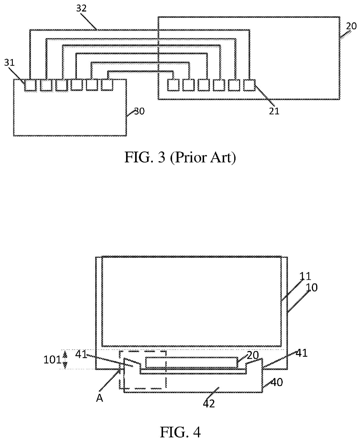
[0019]Please refer to FIGS. 4 to 8. FIG. 4 is a schematic structure view of a display panel of the present invention. A flexible printed circuit board 40 of the present invention is provided to connect a driver chip 20 with a printed circuit board (not shown).

[0020]The flexible printed circuit board 40 includes two first output portions 41 and a first input portion 42. The first input portion 42 and the first output portions 41 each ar...


PUM


Abstract

A flexible printed circuit board, a display panel, and a display device are disclosed. The flexible printed circuit board includes a first input portion, and at least a first output portion disposed on the first input portion. The first input portion and the first output portion are disposed at different sides of the flexible printed circuited board. The first output portion includes a plurality of first output terminals, and each of the first output terminals of the first output portion is spaced apart at a different distance from a top end of the first output portion.

Description

BACKGROUND OF INVENTION1. Field of Invention[0001]The present invention relates to a technical field of displays, and particularly to, a flexible printed circuit board, a display panel, and a display device.2. Related Art[0002]With development of full screens, in order to increase a screen ratio, it is necessary to reduce width of lower boundaries of display screens. As shown in FIG. 1, a current chip on glass (COG) module includes a substrate 10, a display area 11, a driver chip 20 disposed below the display area 11, and a flexible printed circuited board (FPC) 30, wherein a size of a lower frame is composed of a width a of a FPC bonding area, a width between the driver chip and the FPC (a width of wire on area (WOA) area) b, a width c of the driver chip 20, and a width d of fan-out lines of data lines.[0003]However, the frame size of a display panel as described above is relatively large, resulting in a structure developed as shown in FIG. 2. A size of a lower frame of a display p...

Claims


Application Information

Patent Timeline
Patent Type & Authority Applications(United States)
IPC IPC(8): H05K1/11H05K1/02
CPCH05K1/117H05K2201/09027H05K2201/10128H05K1/028H05K1/18H05K1/189H05K1/118H05K3/361
Inventor ZOU, GONGHUALU, YUCHENGYANG, XIANG
Owner WUHAN CHINA STAR OPTOELECTRONICS TECH CO LTD
Why Eureka
Try Eureka