
Rapid polarization tracking in an optical channel

Pending Publication Date: 2022-02-10
NOKIA SOLUTIONS & NETWORKS OY
View PDF0 Cites 5 Cited by
  • Summary
  • Abstract
  • Description
  • Claims
  • Application Information

AI Technical Summary

Benefits of technology

The patent describes an optical receiver that can detect a conventional intensity-modulated signal. It uses a polarization-diversity coherent optical receiver to capture the signal and samples it at a high rate. This allows for the continuous tracking of polarization and the recovery of the data encoded in the signal. The technical effect is improved tracking of polarization and faster data recovery.

Problems solved by technology

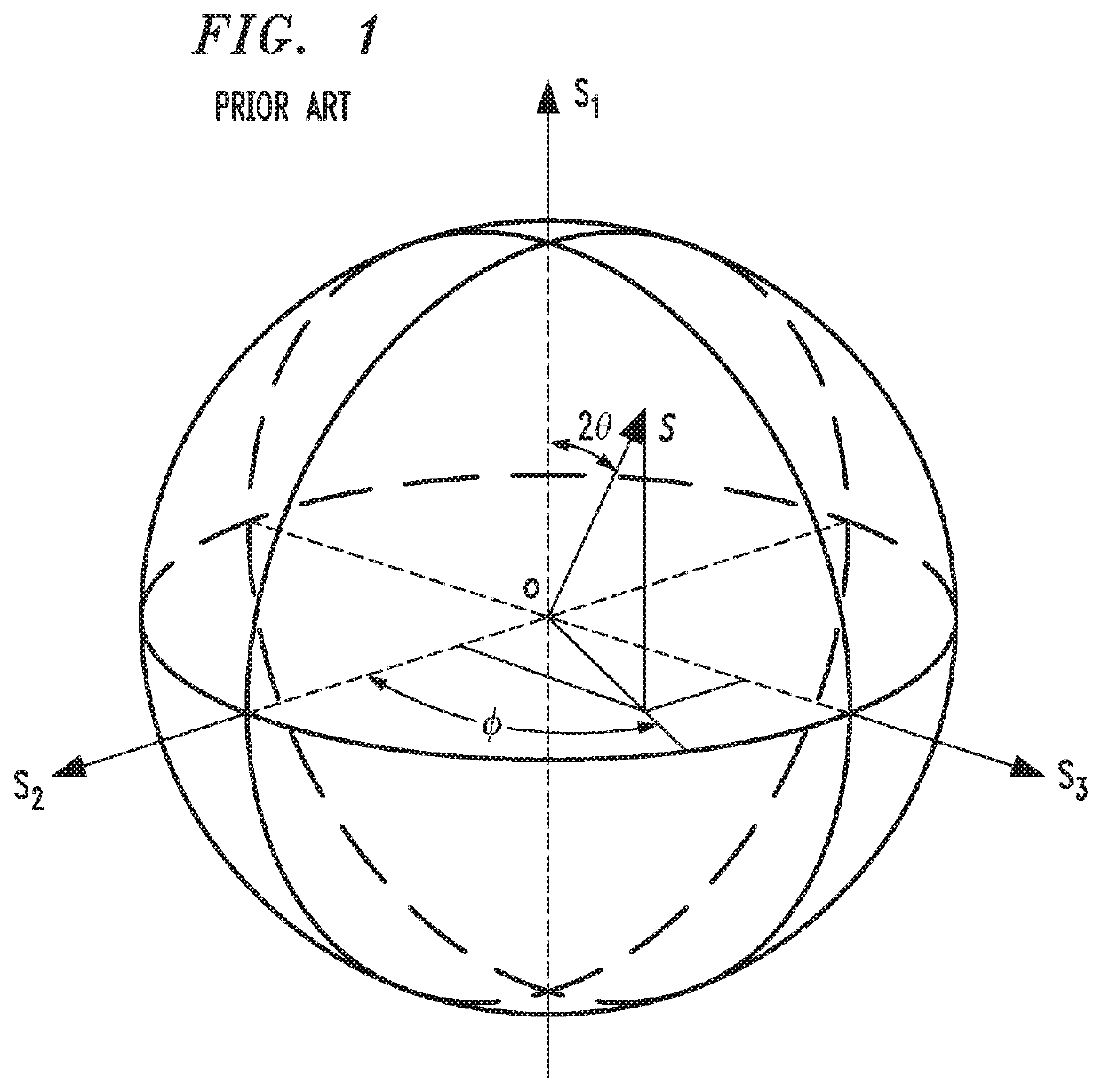
The resulting SOP rotation and polarization-mode-dispersion (PMD) phenomena may lead to signal impairments that can severely limit the transmission capacity of the fiber.
Some ambient events, such as lightning or strong mechanical vibration, may even cause the fiber to rotate the SOP at speeds of several Mrad / s, which can trigger an optical-link outage.

Method used


Image

  • Rapid polarization tracking in an optical channel
  • Rapid polarization tracking in an optical channel
  • Rapid polarization tracking in an optical channel

Examples


Embodiment Construction

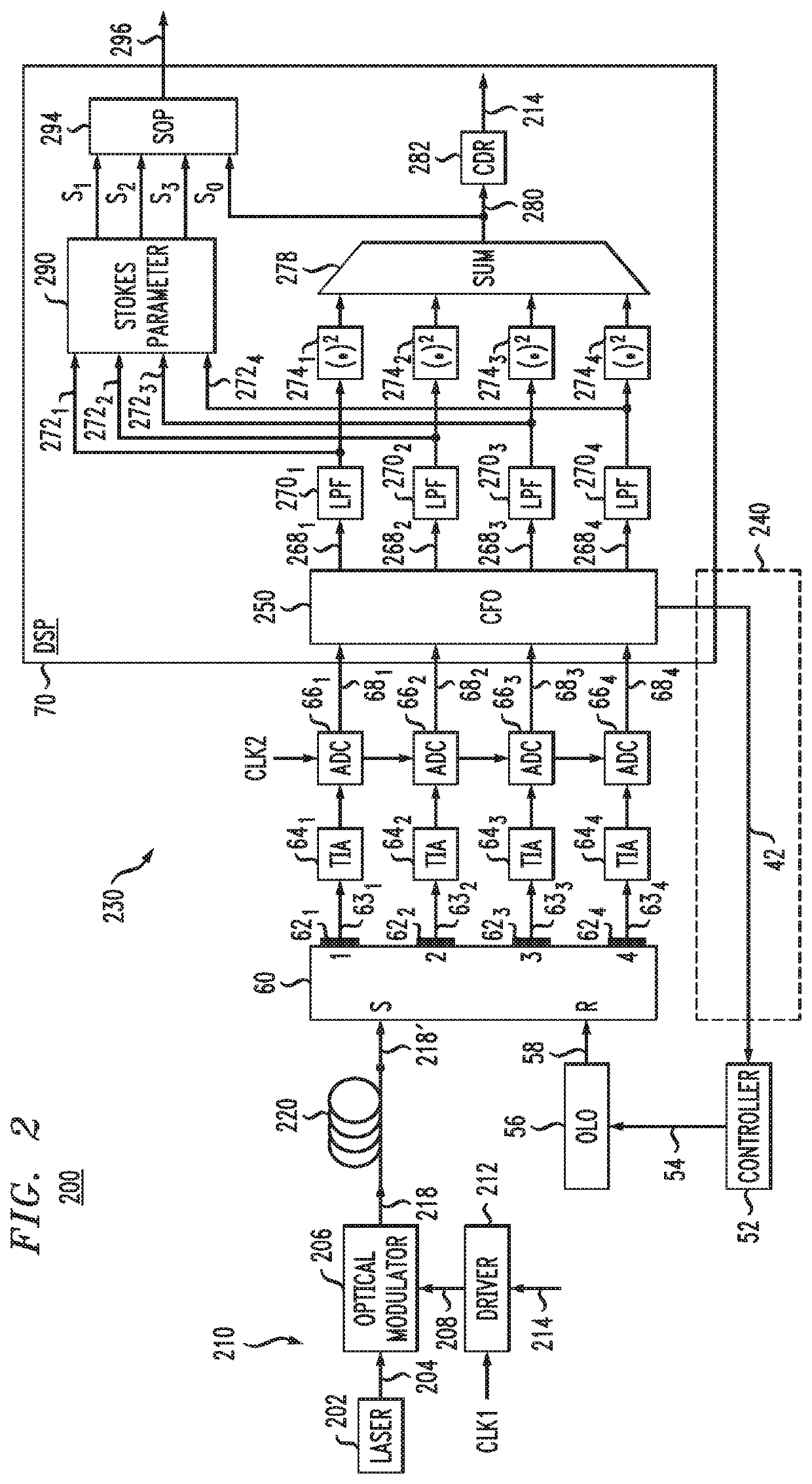
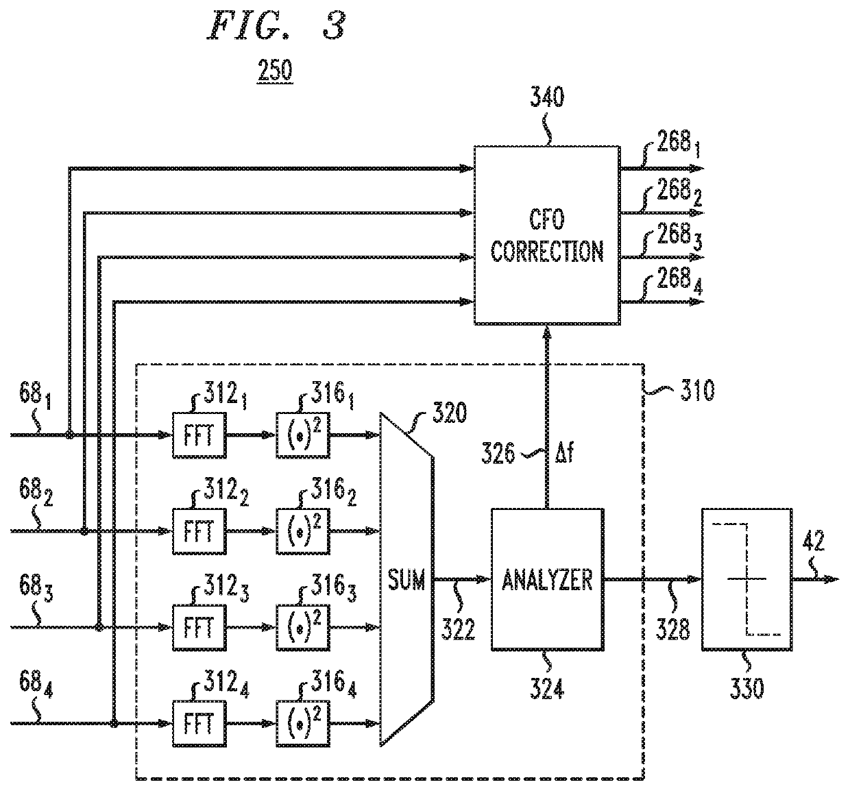
[0004]Disclosed herein are embodiments of an optical receiver, e.g., for an Optical Supervisory Channel (OSC), whose optical front end comprises a polarization-diversity coherent optical receiver configured to receive a conventional intensity-modulated (e.g., OSC) signal. In an example embodiment, four quadrature components of the received OSC signal detected by the polarization-diversity coherent optical receiver are sampled at a relatively high sampling rate and are used to calculate the Stokes parameters of the OSC signal. As a result, the Stokes parameters can be updated at the high sampling rate, which can be suitably selected to enable polarization tracking with a relatively high time resolution and / or at relatively high SOP-rotation speeds. The four detected quadrature components are appropriately combined in the receiver DSP to determine the intensity of the received OSC signal, which is then used in a conventional manner to recover the OSC data encoded therein.

[0005]Some em...


PUM


Abstract

An optical receiver, e.g., for an Optical Supervisory Channel (OSC), whose optical front end comprises a polarization-diversity coherent optical receiver configured to receive a conventional intensity-modulated (e.g., OSC) signal. Four quadrature components of the received OSC signal detected by the polarization-diversity coherent optical receiver are sampled at a relatively high sampling rate and are used to calculate the Stokes parameters of the OSC signal. As a result, the Stokes parameters can be updated at the high sampling rate, which can be suitably selected to enable polarization tracking with a relatively high time resolution and / or at relatively high SOP-rotation speeds. The four detected quadrature components are appropriately combined in the receiver DSP to determine the intensity of the received OSC signal, which is then used in a conventional manner to recover the OSC data encoded therein.

Description

BACKGROUNDField[0001]Various example embodiments relate to optical communication equipment and, more specifically but not exclusively, to state of polarization (SOP) measurements.Description of the Related Art[0002]This section introduces aspects that may help facilitate a better understanding of the disclosure. Accordingly, the statements of this section are to be read in this light and are not to be understood as admissions about what is in the prior art or what is not in the prior art.[0003]A standard single-mode fiber typically supports two modes of propagation distinguished by their polarization. Due to optical birefringence in the fiber, the polarization modes may travel with different group velocities, and random changes in the birefringence along the fiber length typically result in random coupling between the modes. The resulting SOP rotation and polarization-mode-dispersion (PMD) phenomena may lead to signal impairments that can severely limit the transmission capacity of ...

Claims


Application Information

Patent Timeline
IPC IPC(8): H04B10/61H04B10/077H04B10/54H04J14/06
CPCH04B10/614H04B10/077H04B10/503H04B10/541H04J14/06H04B10/6166H04B10/07951H04B10/2569
Inventor LE, THAI SON
Owner NOKIA SOLUTIONS & NETWORKS OY
Learn More