Micro-scanning space-time resolution measurement system

A space-time resolution and measurement system technology, applied in the direction of image conversion/image enlargement tube, screen tube, etc., to achieve the effect of improving spatial resolution, low loss, and high dynamic range

Inactive Publication Date: 2016-04-13
LASER FUSION RES CENT CHINA ACAD OF ENG PHYSICS
View PDF4 Cites 0 Cited by
  • Summary
  • Abstract
  • Description
  • Claims
  • Application Information

AI Technical Summary

Problems solved by technology

[0004] The purpose of the present invention is to provide a micro-scanning space-time resolution measuring system in order to overcome the shortcomings of the existing gated framing technology in terms of spatial resolution

Method used


Image

  • Micro-scanning space-time resolution measurement system
  • Micro-scanning space-time resolution measurement system
  • Micro-scanning space-time resolution measurement system

Examples


Embodiment Construction

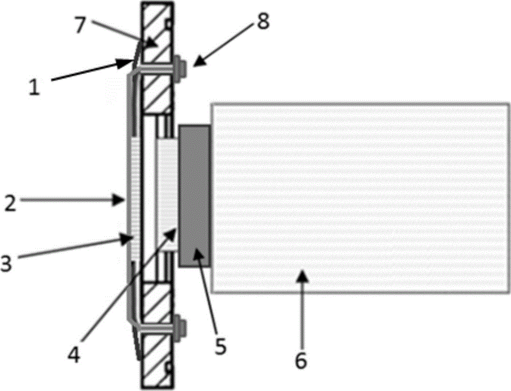
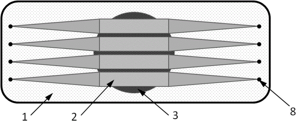
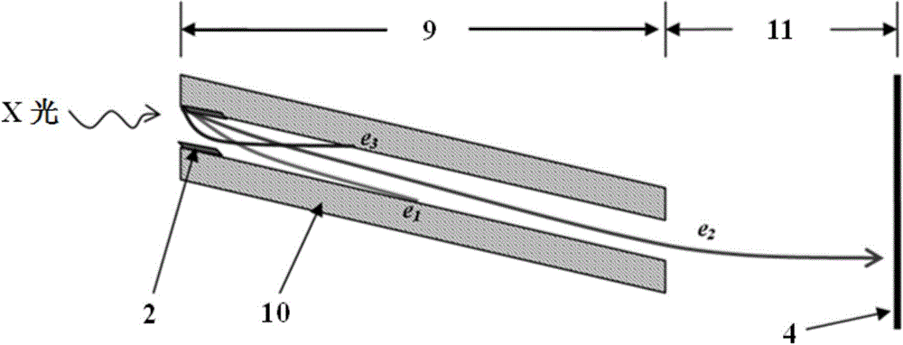
[0021] see figure 1 , with reference to figure 2 , image 3 , Figure 4 , the micro-scanning time-space resolution measurement system of the present invention has a working energy range of 0.1keV-10keV. The measurement system includes a high-voltage power supply, a gate pulse generator and a micro-scan image changer tube. Among them, the structural diagram of the micro-scanning image converter is shown in Figure 1, including PCB substrate 1, cathode microstrip line 2, non-gain micro-channel plate 3, fluorescent screen 4, external intensifier 5, visible light CCD6, disc-shaped flange 7 and coaxial connector 8.

[0022] The non-gain microchannel plate 3 is clamped in the central opening of the PCB substrate 1, and the surface is flush with the PCB substrate 1, and the cathode microstrip lines 2 are plated on the non-gain microchannel plate 3 and the surface of the PCB substrate 1 in parallel and at equal intervals, The cathode microstrip line terminal is connected to the c...


PUM


Abstract

A micro-scanning space-time resolution measuring system comprises a high-voltage power supply, a gate pulse generator and a micro-scanning image converter tube. The micro-scanning image converter tube comprises a disc-shaped flange, a coaxial connector, a PCB substrate, a fluorescent screen, a gain-free microchannel board, a cathode microstrip line, an external intensifier and a visible light CCD. The micro-scanning space-time resolution measuring system is adopted, the transition time of emergent photoelectrons is short, the spatial resolution superior to 5 microns is achieved, and meanwhile the time resolution of the system can be greatly improved.

Description

technical field [0001] The invention relates to a gate control framing technology in ultra-high-speed imaging technology, in particular to a micro-scanning space-time resolution measurement system. Background technique [0002] Ultra-high-speed imaging is an important tool for human beings to explore the unknown world. To some extent, the level of imaging technology can determine the level of physical understanding. The multi-dimensional photography method with high time resolution and high spatial resolution under the same system can provide key experimental observation methods for exploring ultrafast physical processes, plasma physical evolution, celestial body evolution, and biodynamics research. In the current ultra-high-speed imaging technology, there are mainly two technical approaches: one is fringe scanning technology, which can achieve one-dimensional time resolution and one-dimensional spatial resolution; the other is gated framing technology, which is currently ...

Claims


Application Information

Patent Timeline
Patent Type & Authority Patents(China)
IPC IPC(8): H01J31/50
Inventor 曹柱荣邓博
Owner LASER FUSION RES CENT CHINA ACAD OF ENG PHYSICS
Why Eureka
Try Eureka