Grid for a tunnel thruster
a tunnel thruster and grid technology, applied in the direction of marine propulsion, propellant elements of rotary type, vessel parts, etc., can solve the problems of decreasing the thrust of the tunnel thruster, increasing the resistance of the vessel to water movement,
Pending Publication Date: 2022-03-03
ELOMATIC
View PDF0 Cites 0 Cited by
- Summary
- Abstract
- Description
- Claims
- Application Information
AI Technical Summary
Benefits of technology
The present invention provides a grid for a tunnel thruster that reduces resistance to motion in water and increases thrust. The grid is reliable and durable, produces low noise and vibration, and is easy to install. The invention's vessel has a small resistance to motion in water and a large thrust.
Problems solved by technology
A known problem associated with the tunnel thruster is the vessel's increased resistance to motion in water.
Even though these grids decrease the vessel's resistance to motion in water, they also create a problem in the form of the decreased thrust of the tunnel thruster.
Method used
View moreImage
Smart ImageViewing Examples

Examples
first embodiment
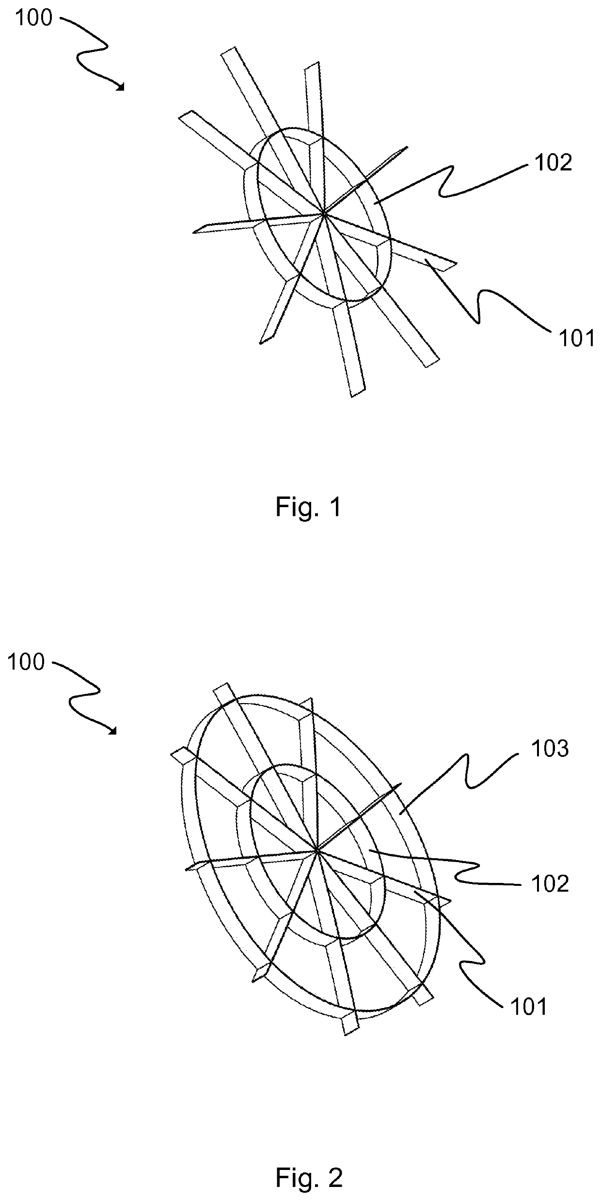
[0056]FIG. 1 illustrates a grid according to the invention,
second embodiment
[0057]FIG. 2 illustrates a grid according to the invention,
third embodiment
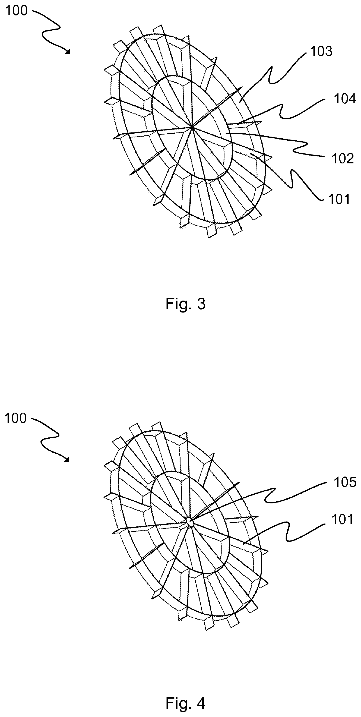
[0058]FIG. 3 illustrates a grid according to the invention,
Login to View More PUM
 Abstract
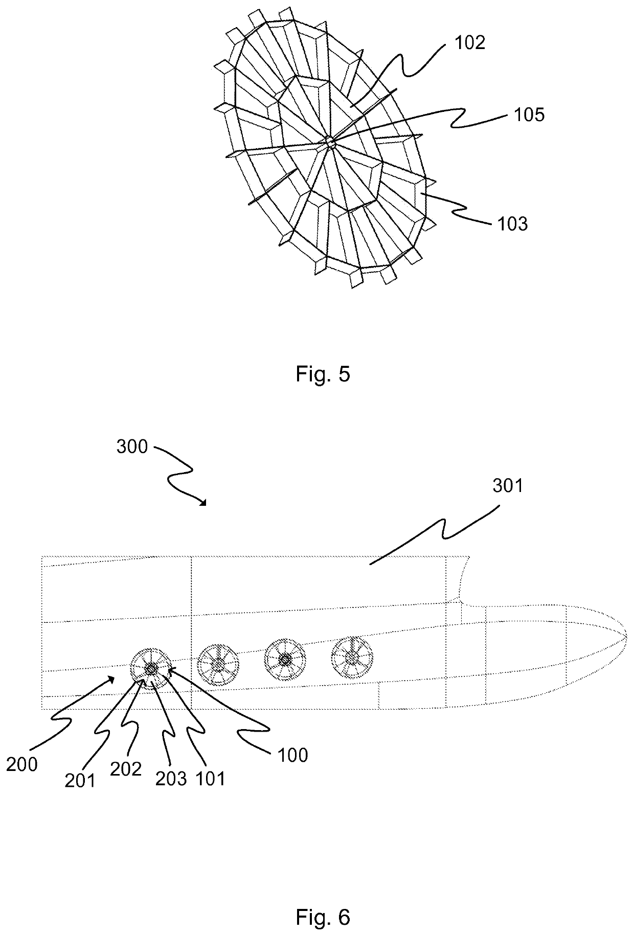
A grid (100) is for a tunnel thruster (200). The grid (100) includes a plurality of first radially extending bars (101) arranged at angular intervals from each other, and a plurality of first connecting bars (102). Each of the first connecting bars (102) are connected between adjacent first radially extending bars (101).
Description
TECHNICAL FIELD OF THE INVENTION[0001]The present invention relates to a grid for a tunnel thruster according to the preamble of the appended independent claim. The invention also relates to a tunnel thruster and a vessel incorporating such a grid.BACKGROUND OF THE INVENTION[0002]Tunnel thrusters, also known as transverse or manoeuvring thrusters, are widely used in vessels, such as ships and boats. A tunnel thruster that is typically installed in the bow or stern of a vessel, below the waterline, provides a transverse thrust to support manoeuvring, mooring, station keeping and dynamic positioning of the vessel.[0003]An exemplary tunnel thruster comprises a tunnel section that is open at both ends. A propeller is mounted inside the tunnel section and it can be rotated by a motor to create a thrust in either direction.[0004]A known problem associated with the tunnel thruster is the vessel's increased resistance to motion in water. A known solution to this problem is to provide the en...
Claims
Login to View More Application Information
Patent Timeline
 IPC IPC(8): B63H5/16B63H1/04
CPCB63H5/165B63H1/04B63B13/02B63H25/42B63H2025/425
Inventor RAUTAHEIMO, PATRIKTANTTARI, JUHA
Owner ELOMATIC
Features
- R&D
- Intellectual Property
- Life Sciences
- Materials
- Tech Scout
- Unparalleled Data Quality
- Higher Quality Content
- 60% Fewer Hallucinations
Learn More Browse by: Latest US Patents, China's latest patents, Technical Efficacy Thesaurus, Application Domain, Technology Topic, Popular Technical Reports.
© 2025 PatSnap. All rights reserved.Legal|Privacy policy|Modern Slavery Act Transparency Statement|Sitemap|About US| Contact US: help@patsnap.com