Supercharge Your Innovation With Domain-Expert AI Agents!

Light irradiation type heat treatment apparatus

a heat treatment apparatus and light irradiation technology, applied in the direction of ohmic-resistance heating devices, basic electric elements, electric devices, etc., can solve the problems of light diffusion plates slipping and moving, different temperature distribution, and air mass entering between contact surfaces

Pending Publication Date: 2022-03-10
DAINIPPON SCREEN MTG CO LTD
View PDF0 Cites 2 Cited by
  • Summary
  • Abstract
  • Description
  • Claims
  • Application Information

AI Technical Summary

Benefits of technology

The present invention aims to prevent a light diffusion plate from sliding during heat treatment of a substrate. This is achieved by using an air escape mechanism that removes air remaining on the contact surfaces of the quartz window and the light diffusion plate, which would otherwise expand and cause the diffusion plate to slide. The technical effect of this mechanism is improved stability and reliability during the manufacturing process of the substrate.

Problems solved by technology

As a result, the in-plane distribution of illuminance becomes nonuniform, which in turn causes variations in temperature distribution.
At this time, minute flaws in the surfaces cause a mass of air to enter between the contact surfaces in some cases.
As a result, a thin layer of air is trapped between the chamber window and the light diffusion plate to give rise to a problem such that the light diffusion plate slips and moves.

Method used


Image

  • Light irradiation type heat treatment apparatus
  • Light irradiation type heat treatment apparatus
  • Light irradiation type heat treatment apparatus

Examples


first preferred embodiment

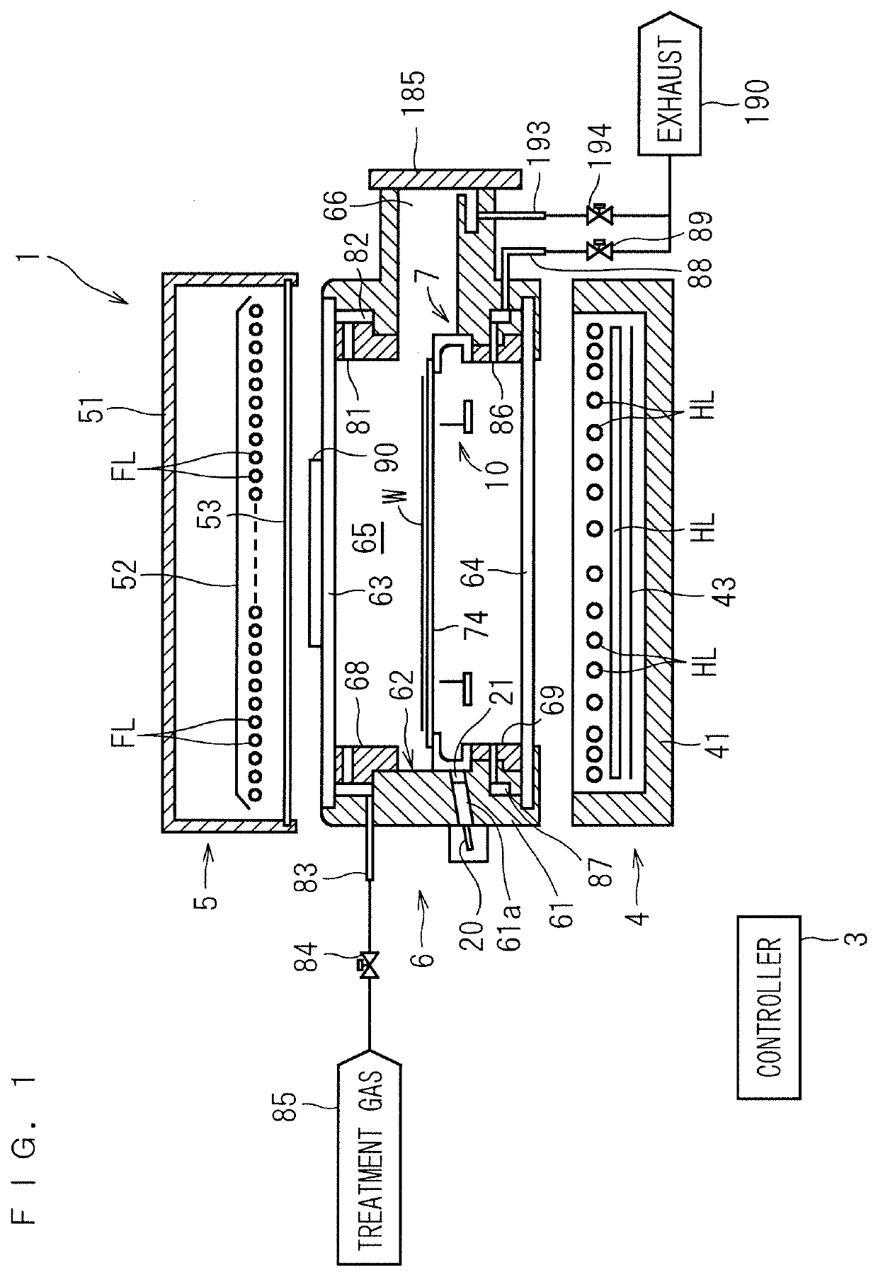
[0027]FIG. 1 is a longitudinal sectional view showing a configuration of a heat treatment apparatus 1 according to the present invention. The heat treatment apparatus 1 of FIG. 1 is a flash lamp annealer for irradiating a disk-shaped semiconductor wafer W serving as a substrate with flashes of light to heat the semiconductor wafer W. The size of the semiconductor wafer W to be treated is not particularly limited. For example, the semiconductor wafer W to be treated has a diameter of 300 mm and 450 mm (in the present preferred embodiment, 300 mm). The semiconductor wafer W prior to the transport into the heat treatment apparatus 1 is implanted with impurities. The heat treatment apparatus 1 performs a heating treatment on the semiconductor wafer W to thereby activate the impurities implanted in the semiconductor wafer W. It should be noted that the dimensions of components and the number of components are shown in exaggeration or in simplified form, as appropriate, in FIG. 1 and the ...

second preferred embodiment

[0080]Next, a second preferred embodiment according to the present invention will be described. The heat treatment apparatus 1 of the second preferred embodiment is generally similar in overall configuration to that of the first preferred embodiment. A procedure for the treatment of a semiconductor wafer W in the heat treatment apparatus 1 of the second preferred embodiment is also similar to that of the first preferred embodiment. The second preferred embodiment differs from the first preferred embodiment in the form of the air escape mechanism.

[0081]FIG. 9 is a sectional view of a light diffusion plate 191 according to the second preferred embodiment. As in the first preferred embodiment, the light diffusion plate 191 is placed on the upper surface of the upper chamber window 63 provided in the upper portion of the chamber 6. In the second preferred embodiment, the light diffusion plate 191 is provided with a plurality of through holes 192 bored therein so as to extend through the...

third preferred embodiment

[0083]Next, a third preferred embodiment according to the present invention will be described. The heat treatment apparatus 1 of the third preferred embodiment is generally similar in overall configuration to that of the first preferred embodiment. A procedure for the treatment of a semiconductor wafer W in the heat treatment apparatus 1 of the third preferred embodiment is also similar to that of the first preferred embodiment. The third preferred embodiment differs from the first preferred embodiment in the form of the air escape mechanism.

[0084]FIG. 10 is a plan view of a light diffusion plate 291 as seen from the lower surface side thereof according to the third preferred embodiment. As in the first preferred embodiment, the light diffusion plate 291 is placed on the upper surface of the upper chamber window 63 provided in the upper portion of the chamber 6. In the third preferred embodiment, a plurality of grooves 292 are formed in the lower surface of the light diffusion plate...


PUM

PropertyMeasurementUnit
diameteraaaaaaaaaa
diameteraaaaaaaaaa
inner diameteraaaaaaaaaa

Abstract

A light diffusion plate is placed on an upper surface of an upper chamber window. A blasting process is applied to a lower surface of the light diffusion plate to provide the lower surface in the form of frosted glass. When the light diffusion plate is placed on the upper surface of the upper chamber window, the light diffusion plate and the upper chamber window do not closely adhere to each other. The frosted glass releases a mass of air entering between contact surfaces of the light diffusion plate and the upper chamber window to the outside even if the mass of air thermally expands during heat treatment. This restrains the occurrence of a phenomenon in which a thin layer of air is trapped between the light diffusion plate and the upper chamber window to prevent the sliding of the light diffusion plate resulting from the air layer.

Description

BACKGROUND OF THE INVENTIONField of the Invention[0001]The present invention relates to a heat treatment apparatus which irradiates a thin plate-like precision electronic substrate (hereinafter referred to simply as a “substrate”) such as a semiconductor wafer with light to heat the substrate.Description of the Background Art[0002]In the process of manufacturing a semiconductor device, attention has been given to flash lamp annealing (FLA) which heats a semiconductor wafer in an extremely short time. The flash lamp annealing is a heat treatment technique in which xenon flash lamps (the term “flash lamp” as used hereinafter refers to a “xenon flash lamp”) are used to irradiate a surface of a semiconductor wafer with a flash of light, thereby raising the temperature of only the surface of the semiconductor wafer in an extremely short time (several milliseconds or less).[0003]The xenon flash lamps have a spectral distribution of radiation ranging from ultraviolet to near-infrared regio...

Claims


Application Information

Patent Timeline
Patent Type & Authority Applications(United States)
IPC IPC(8): H01L21/67
CPCH01L21/67115H05B3/0047H01L21/324H01L21/68707H01L21/68714H01L21/68742H01L21/67017
Inventor UEDA, AKITSUGUMIYAKE, HIROSHIFUSE, KAZUHIKOTANIMURA, HIDEAKI
Owner DAINIPPON SCREEN MTG CO LTD
Features
  • R&D
  • Intellectual Property
  • Life Sciences
  • Materials
  • Tech Scout
  • Unparalleled Data Quality
  • Higher Quality Content
  • 60% Fewer Hallucinations
Learn More