Scanned Laser Vein Contrast Enhancer with Scanning Correlated to Target Distance
What is Al technical title?
Al technical title is built by PatSnap Al team. It summarizes the technical point description of the patent document.
a contrast enhancer and laser vein technology, applied in the field of imaging devices, can solve the problems that no such control is possible, and achieve the effects of increasing the quality of the image captured, accurately detecting the position of blood vessels, and increasing the ability of the system
Pending Publication Date: 2022-03-24
ACCUVEIN
View PDF0 Cites 0 Cited by
Summary
Abstract
Description
Claims
Application Information
AI Technical Summary
This helps you quickly interpret patents by identifying the three key elements:
Problems solved by technology
Method used
Benefits of technology
[0063]One embodiment of a system that uses repeatable scanning is one in which the image is averaged across two or more frames, thereby increasing the quality of the image captured and therefore increases the ability of the system to accurately detect the position of blood vessels.
[0064]Many patterns of scanning are possible. For example, the patterns can be based on raster, collapsing ellipse, spirals, lissajous or random. Tradeoffs between pattern and system complexity can be made to create multiple products of differing cost and performance. For example, if the mirrors are run at their natural resonance frequency, the system minimizes the power needed to move the mirrors thereby either extending battery life or reducing the battery size needed and thereby reducing size, weight and cost.
Problems solved by technology
In a camera based solution, since the infrared light floods the area being scanned, no such control is possible.
Method used
Image
Click on the blue label to locate the original text in one second.
Reading with bidirectional positioning of images and text.
Examples
Embodiment Construction
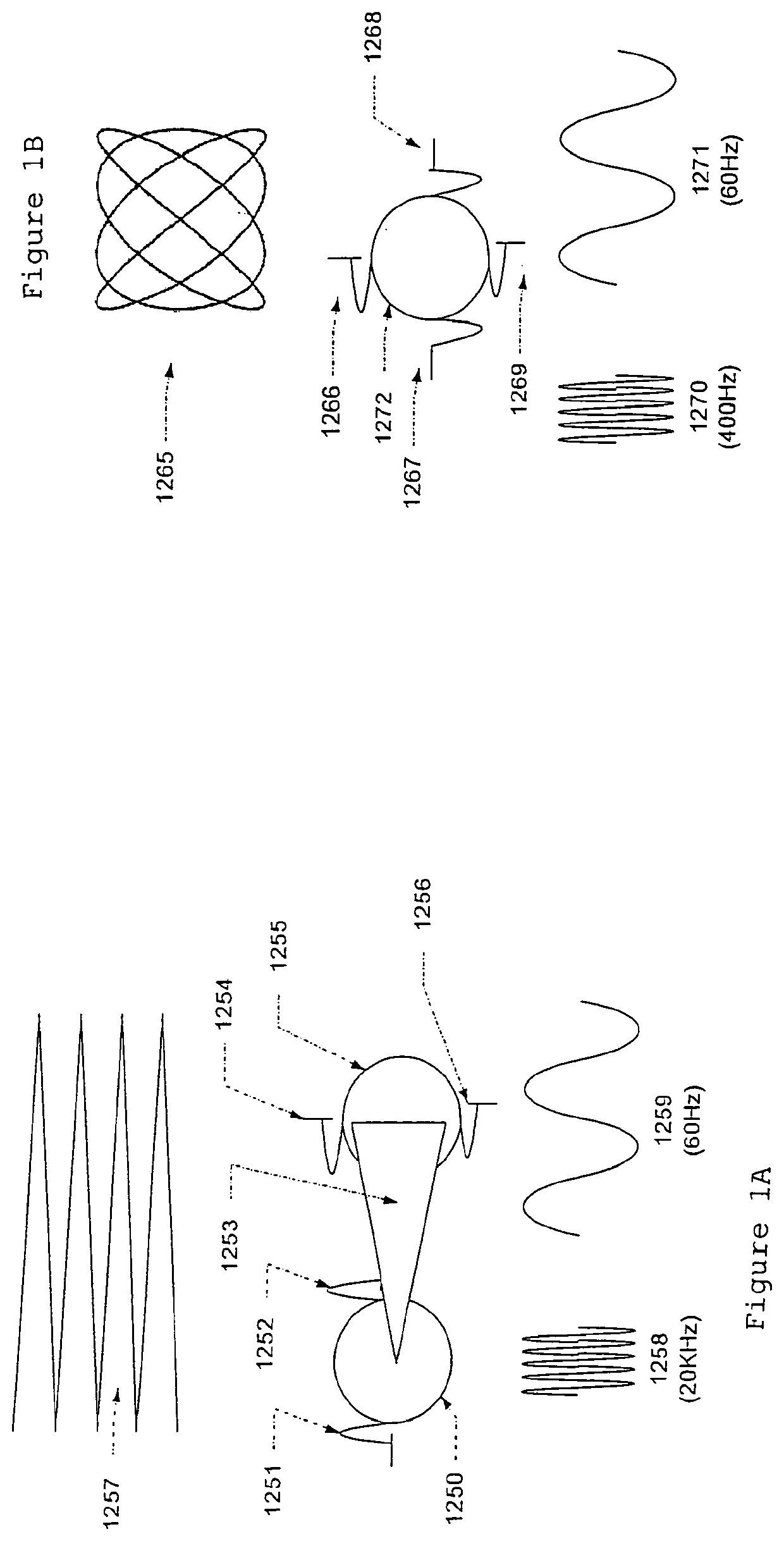
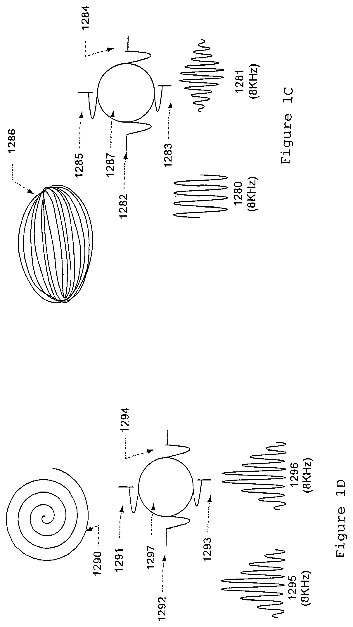
[0065]Referring to FIG. 1a-1d, preferred embodiments are shown that generate raster, lissajous and collapsing ellipse and spiral patterns. The drawings show the mirror (e.g., 1250) on top of the electrical wave form (e.g., 1258) that is applied to the mirror to control its motion. These sinusoidal wave forms move the mirror in a back and forth pattern with maximum deflection at the peak of the wave, rest at the center of the wave and the opposite maximum deflection at the opposite peak of the wave. Also indicated in the drawing are the most preferred frequencies and the preferred ranges that would be used in an implementation of the invention.
Raster Pattern Generation
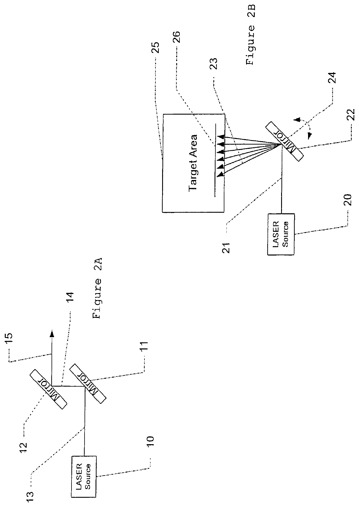
[0066]In FIG. 1a, a raster pattern 1257 is generated using two mirrors. Mirror 1250 is mounted so that it has a single degree of freedom of motion at fulcrum 1251 / 1252. A laser light source as described elsewhere strikes the mirror at an appropriate angle so that the angle of reflection is such that the light properly s...
PUM
Abstract
A portable hand-held miniature vein enhancer comprises: a housing, laser, one or more mirrors, mirror drive system, and sensor to determine a distance to the target. The laser emits a beam of light at a selective wavelength that images subcutaneous veins through differential absorption and reflection. The mirror(s) receive the beam of light and create a spot of light on the target, and when driven by the mirror drive system to oscillate, the spot is scanned to form a two-dimensionally shaped pattern of light. The scanned spot of light moves according to a range of angular positions of the mirror(s). When the distance to the target is at or below a threshold distance, the range of angular positions is set to a maximum, producing the largest scan pattern. When the distance increases beyond the threshold, the range of angular positions is reduced proportional to the increased distance.
Description
CROSS-REFERENCE TO RELATED APPLICATIONS[0001]This is a continuation of U.S. application Ser. No. 15 / 819,218, filed on Nov. 21, 2017, which is a continuation of U.S. application Ser. No. 13 / 648,465, filed on Oct. 10, 2012, now issued as U.S. Pat. No. 9,854,977, which is a continuation of U.S. application Ser. No. 11 / 807,064, filed on May 25, 2007, now issued as U.S. Pat. No. 8,391,960, which claims priority on U.S. Provisional Application Ser. No. 60 / 817,623, also filed on Jun. 29, 2006, entitled “Three Dimensional Imaging of Veins,” and which is also a continuation in part of U.S. application Ser. No. 11 / 478,322, filed on Jun. 29, 2006, now issued as U.S. Pat. No. 8,478,386, which claims priority of U.S. Provisional Application Ser. No. 60 / 757,704, filed on Jan. 10, 2006, all disclosures of which are incorporated herein by reference.FIELD OF INVENTION[0002]The invention described herein relates generally to an imaging device, in particular, an imaging means for enhancing visualizati...
Claims
Application Information
Patent Timeline
Application Date:The date an application was filed.
Publication Date:The date a patent or application was officially published.
First Publication Date:The earliest publication date of a patent with the same application number.
Issue Date:Publication date of the patent grant document.
PCT Entry Date:The Entry date of PCT National Phase.
Estimated Expiry Date:The statutory expiry date of a patent right according to the Patent Law, and it is the longest term of protection that the patent right can achieve without the termination of the patent right due to other reasons(Term extension factor has been taken into account ).
Invalid Date:Actual expiry date is based on effective date or publication date of legal transaction data of invalid patent.
Patent Type & Authority Applications(United States)