Balloon catheter

Pending Publication Date: 2022-03-31
GOODMAN & COMPANY
View PDF0 Cites 0 Cited by
  • Summary
  • Abstract
  • Description
  • Claims
  • Application Information

AI Technical Summary

Benefits of technology

[0018]Thus, in view of the above point, according to the present aspect, a protrusion is formed on the film at a position corresponding to the notch in the linear part, protruding to the inner circumferential side of t

Problems solved by technology

This might make introduction work difficult due to an increase in resistance against the balloon being introduced into the body.
This greatly reduces trackability along the curved blood vess

Method used


Image

  • Balloon catheter
  • Balloon catheter
  • Balloon catheter

Examples


Embodiment Construction

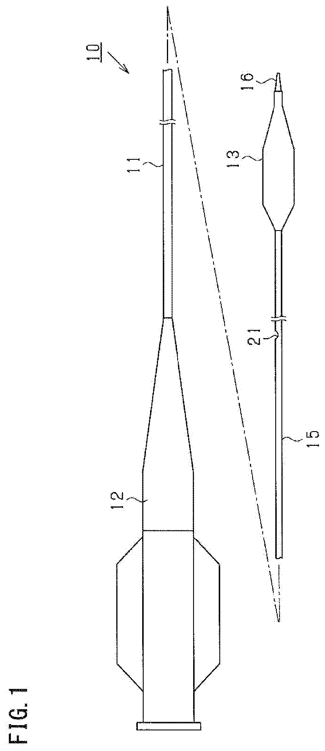
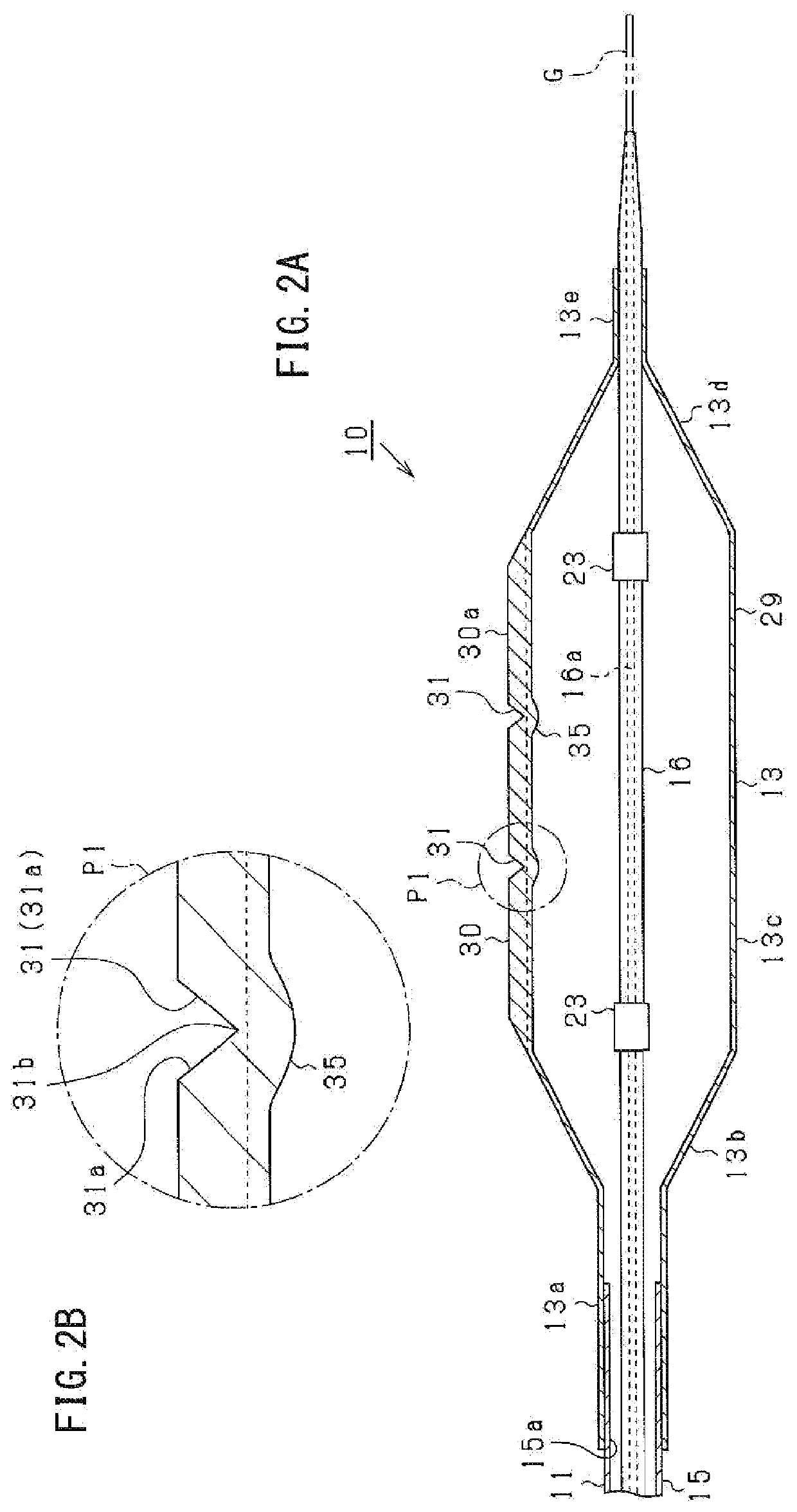
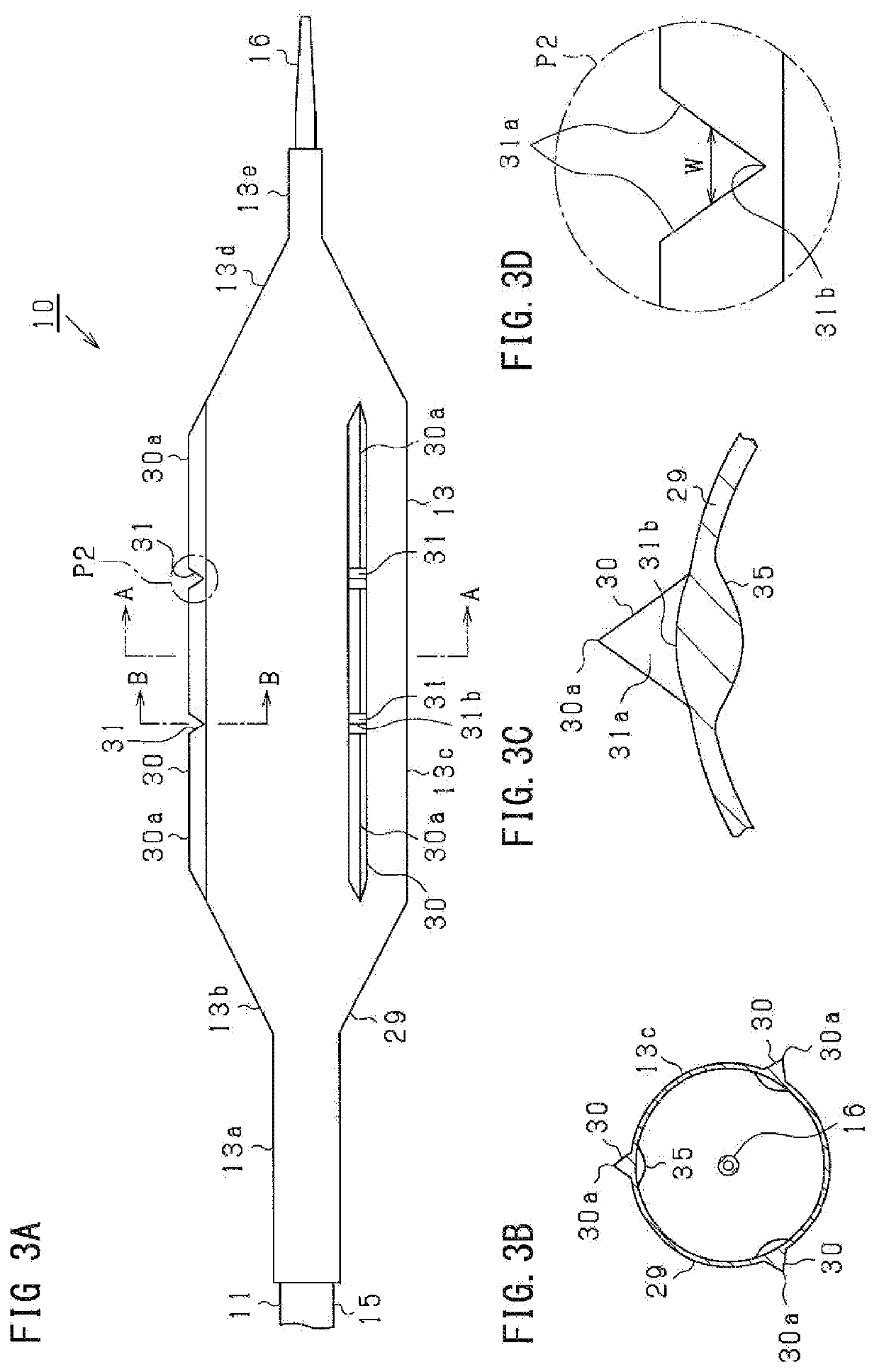
[0024]Embodiments of a balloon catheter will be described below based on the drawings. First, a schematic configuration of a balloon catheter 10 will be described with reference to FIG. 1. FIG. 1 is a schematic overall side view showing a configuration of the balloon catheter 10.

[0025]As shown in FIG. 1, the balloon catheter 10 includes a catheter body 11, a hub 12 attached to a base-end portion (proximal-end portion) of the catheter body 11, and a balloon attached on a tip-end side (distal-end side) of the catheter body 11.

[0026]The catheter body 11 includes an outer tube 15, and an inner tube 16 inserted in the outer tube 15. The outer tube 15 is formed of a resin material such as polyamide elastomer. The outer tube 15 is bonded to the hub 12 in a base-end portion, and to the balloon 13 in a tip-end portion. Besides, the outer tube 15 has a lumen 15a (see FIG. 2A) inside extending all through the outer tube 15 in the axial direction. The lumen 15a is communicated into the hub 12 a...


PUM


Abstract

A balloon catheter includes an inflatable balloon disposed on a tip-end side of the balloon catheter. A linear part of an outer surface of the inflatable balloon extends linearly in an axial direction of the inflatable balloon, the linear part has a notch at an intermediate position in a length direction of the linear part, and the notch opens in a direction intersecting the length direction.

Description

CROSS-REFERENCE TO RELATED APPLICATION[0001]The present application claims priority from Japanese Patent Application No. 2019-115743 filed on Jun. 21, 2019, the contents of which are incorporated herein by reference in their entirety.BACKGROUNDTechnical Field[0002]The present disclosure relates to a balloon catheter.Description of Related Art[0003]A balloon catheter has been used for remedies such as PTA (percutaneous transluminal angioplasty) and PTCA (percutaneous transluminal coronary angioplasty), etc. The balloon catheter includes an inflatable and deflatable balloon on a tip-end side thereof. As for the balloon catheter, the balloon in a deflated state is introduced into a spot narrowed or obstructed by a lesion or the like produced in a blood vessel and then the spot is stretched by inflating the balloon.[0004]Some balloon catheters are provided with a linear element extending in an axial direction to an outer surface of the balloon (for example, see Patent Literature 1). Whe...

Claims


Application Information

Patent Timeline
IPC IPC(8): A61M25/10
CPCA61M25/1002A61M2025/1086A61M2025/1004A61M25/104A61M2025/109A61M25/10
Inventor OKAMOTO, MITSUMASAOTA, MITSUHIROFUJISAWA, SOICHIROOHARA, MASAHIKOHORIBA, KEITAROKUNISADA, TAKASHI
Owner GOODMAN & COMPANY
Why Eureka
Try Eureka