This helps you quickly interpret patents by identifying the three key elements:
Problems solved by technology
Method used
Benefits of technology
Benefits of technology
The patent text describes a lighting device that is protected from external influences by being located inside a form element or connected to it. This allows for the lighting device to be placed at any position on the outside of a vehicle by setting up a corresponding region. The technical effect of this invention is that it provides a more robust and flexible way to protect and install lighting devices on vehicles.
Problems solved by technology
However, it has been shown that although the state of the art lighting fixtures generally offer good safety, they are not optimally suited for lateral illumination of the vehicle, as there is often not enough space available for the arrangement of conventional lighting fixtures.
In addition, previously known lighting devices are often not very flexible with regard to individual design specifications and are therefore expensive to use if they are to be used in a large number of different models of motor vehicles.
This means that even in the case of covering devices with the same shape element, a change in the light emitted from the covering device can only be achieved by varying the covering element.
Method used
Image
Click on the blue label to locate the original text in one second.
Reading with bidirectional positioning of images and text.
Examples
Embodiment Construction
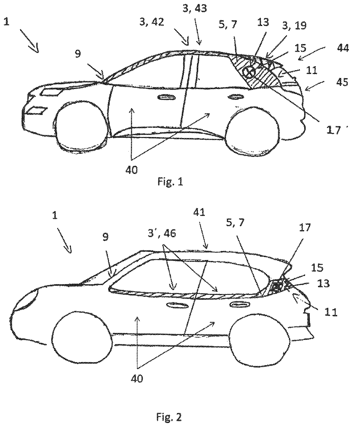
[0057]FIG. 1 shows a schematic representation of a motor vehicle 1 according to the third aspect of the invention in a first form. This has an inventive covering device 3 according to the first aspect of the invention in a first execution form.
[0058]The covering device 3, shown here as a one-piece covering device, comprises a form element 5 which can be produced by an injection moulding process and which reproduces the desired shape of the corresponding side section of the motor vehicle 1. The form element 5 is covered with a covering element 7 in the form of a chrome coating. Covering element 7 covers or is arranged on the entire surface area of the form element 5 pointing outwards. In FIG. 1, the corresponding area is highlighted hatched. This clearly shows that the covering device 3 extends laterally and longitudinally of the motor vehicle 1 as a roof trim 42 above the door area 40, from a position 9 in the area of the A-pillar of the motor vehicle 1 continuously to a position 11...
PUM
Abstract
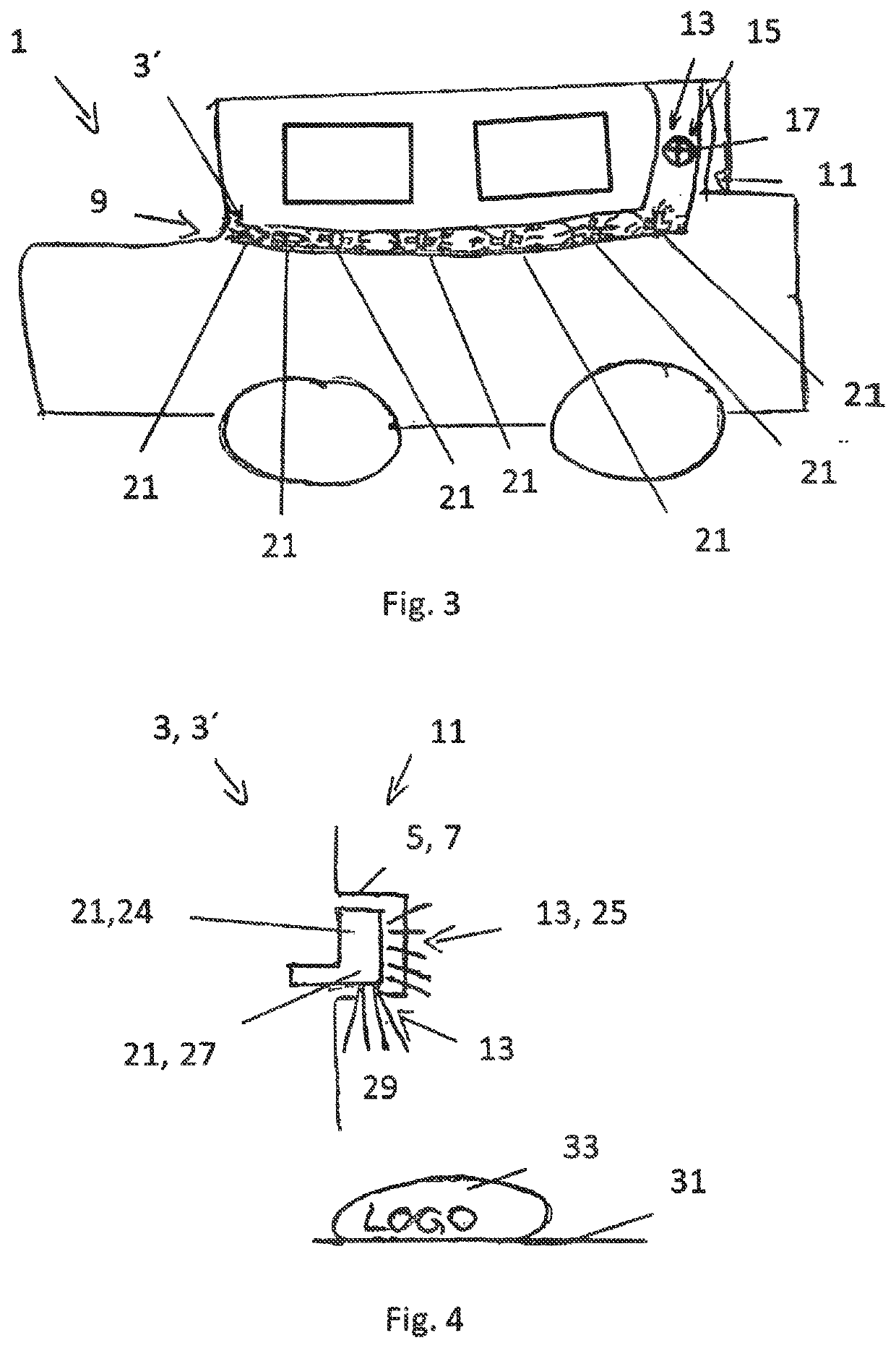
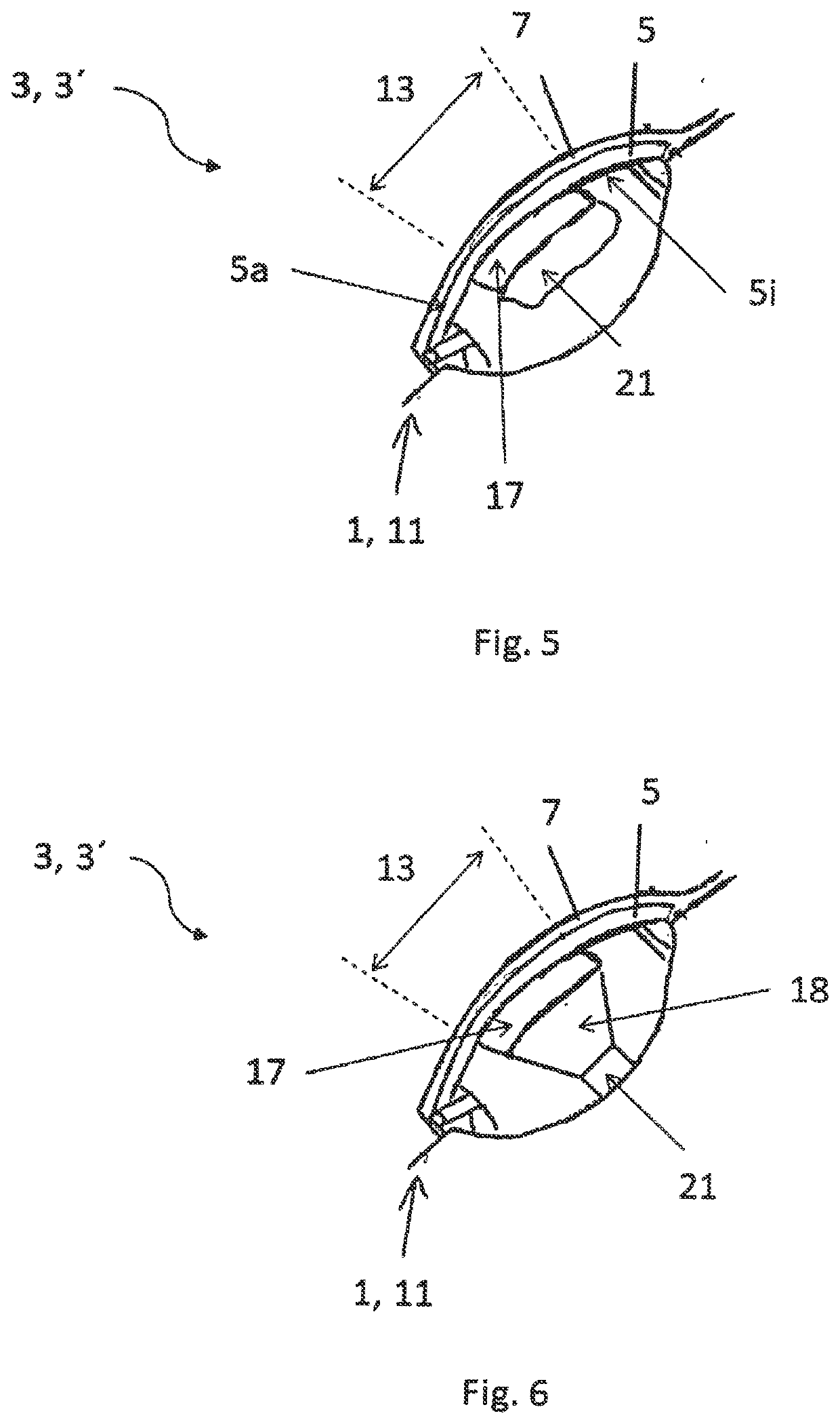
The present invention relates to a covering device 3 for arrangement on at least one outer or one inner region of a motor vehicle 1, comprising at least one form element 5 which is produced and / or can be produced by means of injection moulding and has an inner side 5i oriented towards the motor vehicle and an outer side 5a oriented away from the motor vehicle 1, one or more lighting devices 21, 24, 27 for emitting light and at least one covering element 7 which, for covering the form element 5 at least in regions, is arranged at least in regions on the outer side 5a of the form element 5, at least part of the light emitted by the lighting device 21, 24, 27 being able to pass through the form element 5 and / or the covering element 7 in at least one first region 13 of the covering device 3, the form element 5 and the covering element 7 being at least translucent at least in the first region 13.
Description
BACKGROUND1. Field of the Invention[0001]The present invention relates to a covering device for arrangement on at least one outer or one inner region of a motor vehicle, a bodywork component for a motor vehicle comprising such a covering device and a motor vehicle comprising such a covering device and / or such a bodywork component.2. Related Art[0002]In order to improve road safety, motor vehicles are known to have different means of lighting, for example to illuminate the road area in front of the vehicle or to ensure that the vehicle itself can be seen by other road users by means of appropriate rear lamps. However, it has been shown that although the state of the art lighting fixtures generally offer good safety, they are not optimally suited for lateral illumination of the vehicle, as there is often not enough space available for the arrangement of conventional lighting fixtures. In addition, previously known lighting devices are often not very flexible with regard to individual ...
Claims
Application Information
Patent Timeline
Application Date:The date an application was filed.
Publication Date:The date a patent or application was officially published.
First Publication Date:The earliest publication date of a patent with the same application number.
Issue Date:Publication date of the patent grant document.
PCT Entry Date:The Entry date of PCT National Phase.
Estimated Expiry Date:The statutory expiry date of a patent right according to the Patent Law, and it is the longest term of protection that the patent right can achieve without the termination of the patent right due to other reasons(Term extension factor has been taken into account ).
Invalid Date:Actual expiry date is based on effective date or publication date of legal transaction data of invalid patent.
