
Method for controlling a wind power installation

Pending Publication Date: 2022-04-07
WOBBEN PROPERTIES GMBH
View PDF0 Cites 0 Cited by
  • Summary
  • Abstract
  • Description
  • Claims
  • Application Information

AI Technical Summary

Benefits of technology

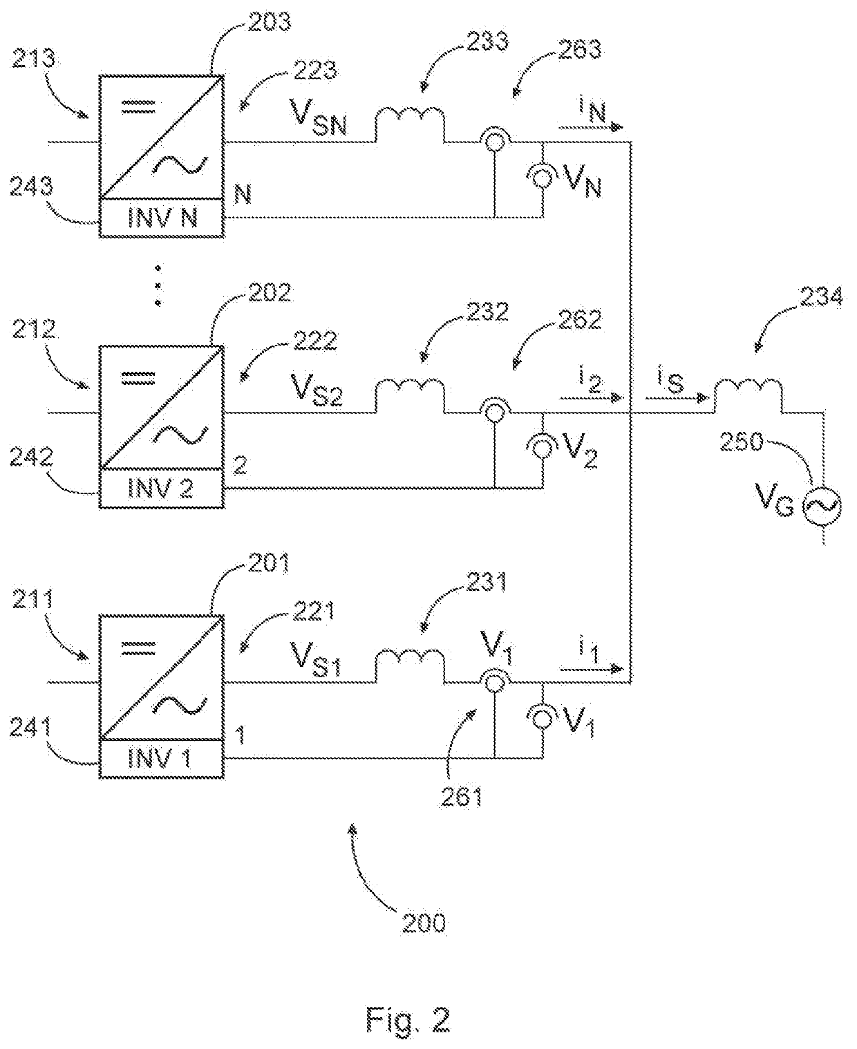
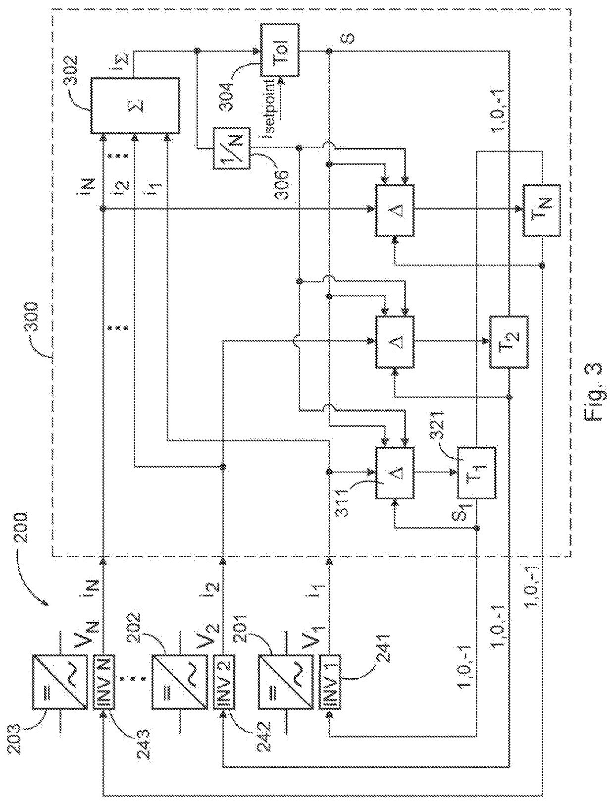
The patent text describes a method for connecting inverters in parallel using a low-inductance method called hysteresis. This method prevents circulating currents that can affect control of individual sub-rectifiers. The overall current is measured using a sensor, but the "summation current" is generated by combining measurements of individual partial currents. This helps to avoid the need for a total current sensor. By using a hysteresis method and small partial inductances, the system is less expensive and easier to control. The partial current in each sub-rectifier can be increased by adjusting the voltage pulse and partially inductance. This method allows for more efficient and accurate control of current in a power conversion system.

Problems solved by technology

This results in the risk of circulating currents arising.
The problem of the circulating currents can in this case arise particularly with inverters that carry out current control using a hysteresis method.
In the case of circulating currents, the problem then arises that, in each sub-inverter, the detected partial current that is intended to be guided there in the prescribed tolerance band can have components of a circulating current.
This can thus disadvantageously influence the current control.
However, such inductances may be undesirable, in particular because they may be a costly component.

Method used


Image

  • Method for controlling a wind power installation
  • Method for controlling a wind power installation
  • Method for controlling a wind power installation

Examples


Embodiment Construction

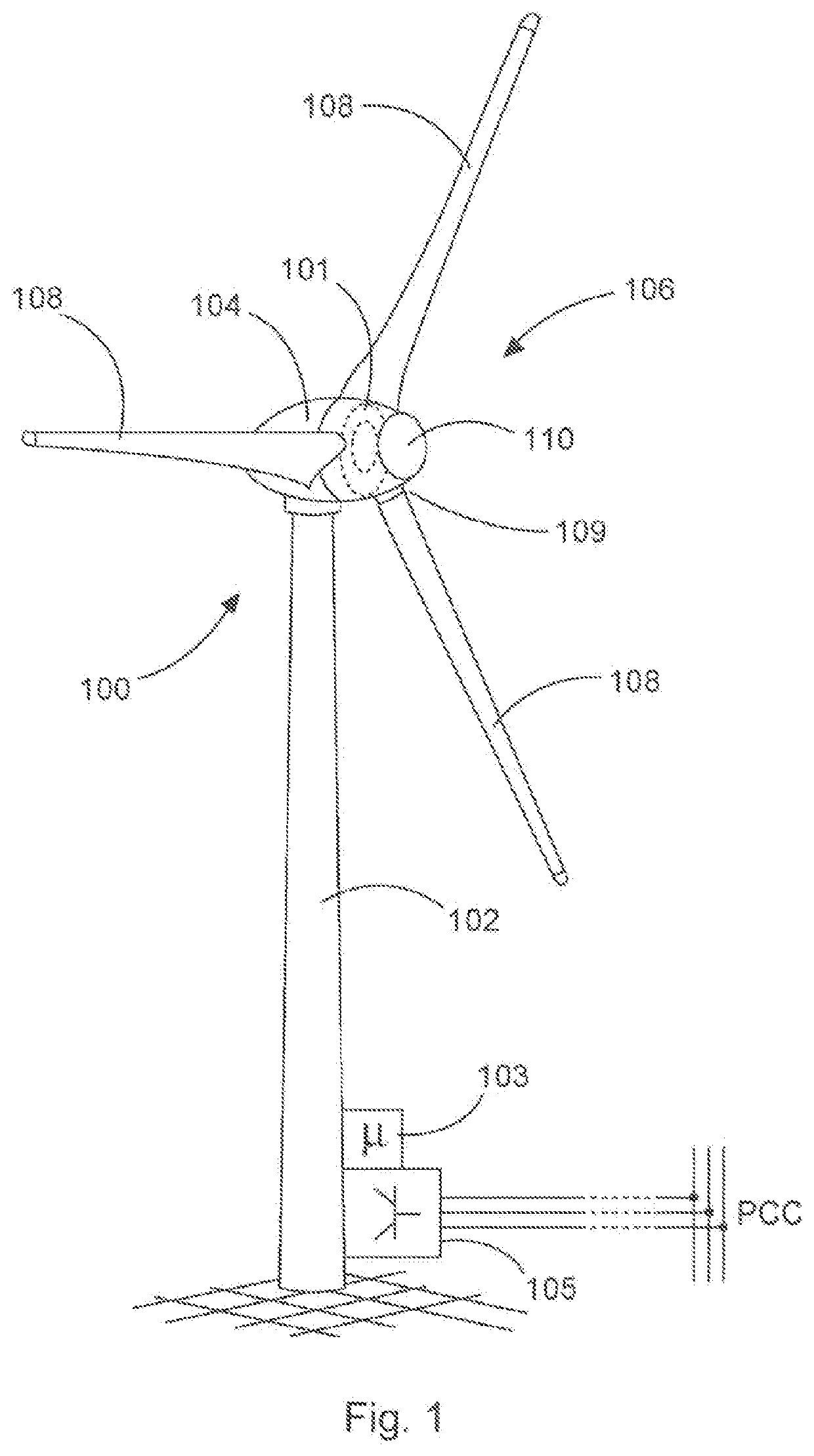
[0084]FIG. 1 shows a schematic illustration of a wind power installation. The wind power installation 100 has a tower 102 and a nacelle 104 on the tower 102. An aerodynamic rotor 106 having three rotor blades 108 and having a spinner 110 is provided on the nacelle 104. During the operation of the wind power installation, the aerodynamic rotor 106 is set in rotational motion by the wind and thereby also rotates an electrodynamic rotor or armature of a generator, which is coupled directly or indirectly to the aerodynamic rotor 106. The electric generator is arranged in the nacelle 104 and generates electrical energy. The pitch angles of the rotor blades 108 can be varied by pitch motors at the rotor blade roots 109 of the respective rotor blades 108.

[0085]The wind power installation 100 in this case has an electric generator 101, which is indicated in the nacelle 104. Electrical power can be generated by means of the generator 101. An infeed unit 105, which can be designed, in particu...


PUM


Abstract

Provided is a method for controlling a wind power installation. The wind power installation includes a generator for generating a generator current with one or more generator current phases, and an active rectifier for rectifying and controlling the generator current. For each generator current phase the rectifier has a plurality of controllable sub-rectifiers. Each controllable sub-rectifier is characterized by a partial inductance, each controllable sub-rectifier controls a partial current of the generator current phase and each generator current phase forms a summation current as a sum of all the partial currents of the relevant generator current phase. The active rectifier is controlled so that for each generator current phase the summation current is detected and each controllable sub-rectifier of the relevant current phase controls the partial current thereof depending on the detected summation current.

Description

BACKGROUNDTechnical Field[0001]The present invention relates to a method for controlling a wind power installation and the invention relates to a corresponding wind power installation.Description of the Related Art[0002]Wind power installations are known, and these generate electrical power from wind by means of a generator and feed same into an electrical supply network. A common topology of such a wind power installation operates in such a way that the generator generates an alternating current, this alternating current is rectified and from this rectified current, which is usually provided in this case in a DC link, the alternating current to be fed in is generated by means of an inverter.[0003]Modern wind power installations are characterized by a rated power of several megawatts (MW). In order to rectify such a power generated by a generator, several rectifiers can be connected in parallel. If these rectifiers are actively controlled and hence also actively control the correspo...

Claims


Application Information

Patent Timeline
IPC IPC(8): F03D9/25H02J3/38
CPCF03D9/25F05D2220/762H02J2300/28H02J3/381H02M7/23H02M7/493H02P2101/15H02P9/00H02M1/0009H02M1/0025H02J3/46Y02E10/72Y02E10/76H02J3/472H02J3/48H02J3/50H02J2300/20
Inventor BAKKER, MENKO
Owner WOBBEN PROPERTIES GMBH
Learn More