Floating plate capacitor with extremely wide band low impedance

Inactive Publication Date: 2001-08-07
THE BOARD OF TRUSTEES OF THE UNIV OF ARKANSAS
View PDF28 Cites 72 Cited by
  • Summary
  • Abstract
  • Description
  • Claims
  • Application Information

AI Technical Summary

Benefits of technology

These capacitors preferably are used in decoupling applications, which applications can advantageously utilize the low-inductance nature of the floating plate capacitor and its method of attachement. The extremely high insertion loss, i.e., decoupling effectiveness' of these capacitors is maintained at frequencies exceeding 1 GHz, even over a wide band from about 1 GHz to 10 GHz.

Problems solved by technology

However, as clock frequencies have increased to above 100 MHz, conventional capacitors are limited.
The problem is that in reality, capacitors also exhibit inductance and resistance components, and this inductance becomes a problem at higher frequencies.
Also detrimental to effective decoupling is the inductance between the IC (integrated circuit) chip itself and the printed circuit wiring board power distribution planes to which the decoupling capacitors are connected.
Connecting many leads in parallel to power and ground connections does not totally eliminate this effect.
If large current swings are required by the IC circuitry, this residual inductance can cause unacceptable voltage drops and AC noise.
Similarly, the intrinsic inductance and resistance of power distribution planes, either solid, perforated, or the new IMPS (interconnected mesh power system), is extremely low, and does not determine the effectiveness of power distribution.
However, these capacitors are expensive to fabricate and contribute significantly to substrate defects.
The need to distribute multiple voltages (e.g., 3.3V, 5V, etc.) makes their use prohibitive in many applications.
But again, such structures are expensive to produce, and do not work with many sets of packaging materials.
Unfortunately, the wirebond connections are still significantly inductive, and the silicon-based capacitors are expensive.

Method used


Image

  • Floating plate capacitor with extremely wide band low impedance
  • Floating plate capacitor with extremely wide band low impedance
  • Floating plate capacitor with extremely wide band low impedance

Examples


Embodiment Construction

As described above, the present invention provides discrete floating plate capacitors, manufactured with as little as one patterning step, preferably for decoupling applications which can utilize the low-inductance nature of the inventive capacitors to advantage.

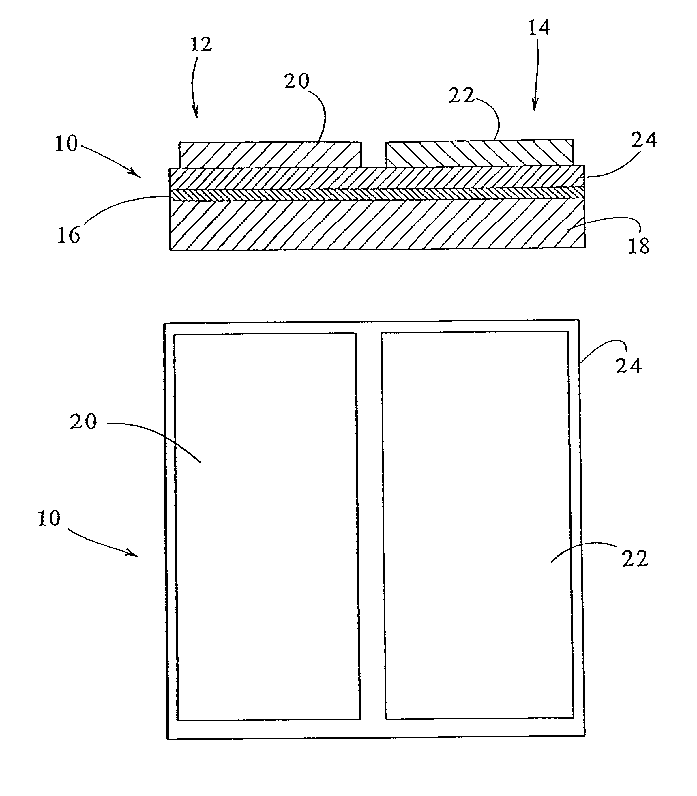
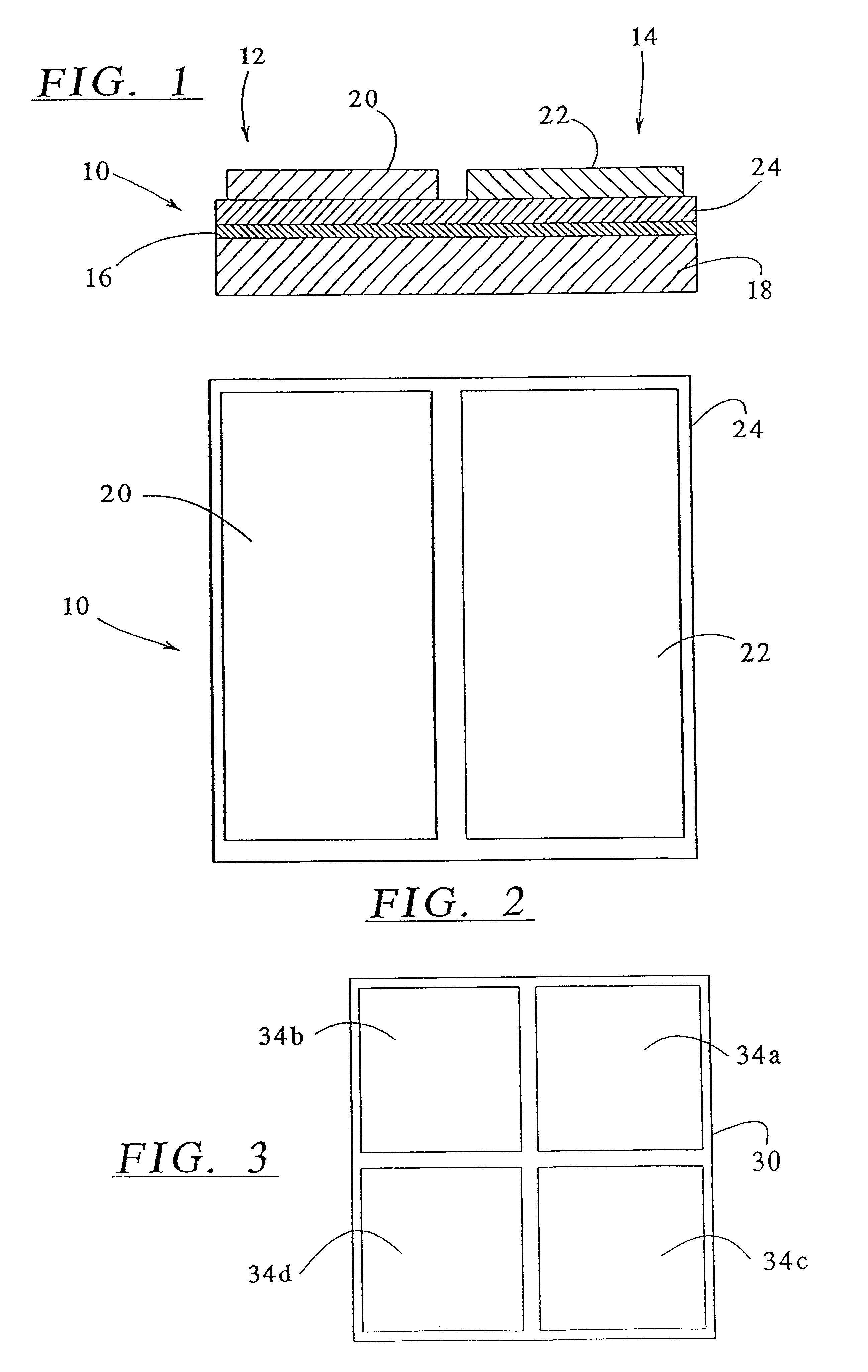
A floating plate capacitor 10 embodying principles of the invention is illustrated in FIGS. 1 and 2. There it can be seen that the floating plate capacitor 10 basically comprises two parallel plate capacitors 12 and 14 positioned side-by-side. The capacitors 12 and 14 have a common floating plate 16 supported on an insulating substrate 18, and separate patterned plates 20 and 22 positioned side-by-side above an intervening dielectric layer 24. Connections to the capacitor 10 are made via optional terminal pads formed on the plates 20 and 22.

It will be appreciated that if the total area of the two capacitors 12 and 14 is A, there are effectively two capacitors connected in series, each having an area A / 2. Thus, whatever capac...


PUM

PropertyMeasurementUnit
Frequencyaaaaaaaaaa
Frequencyaaaaaaaaaa
Insertion lossaaaaaaaaaa

Abstract

A capacitor exhibits high two-port insertion loss even at frequencies as high as 10 GHz. Notably, the capacitor exhibits an insertion loss of more than -40 dB over a range from 1 GHz to 10 GHz and no inductive resonance below a frequency of at least 1 GHz.

Description

BACKGROUND OF THE INVENTIONThe present invention is directed to parallel plate capacitors as well as decoupling capacitors for semiconductor applications. More specifically, the invention is directed to discrete, low inductance capacitors typically used in decoupling applications.The purpose of power distribution systems is to deliver stable, noise-free power to integrated circuits (ICs) and other devices. One way to express this quantitatively is that the power distribution impedance, as seen from a chip, must be less than some value, over whatever frequency range is of interest. The value is determined by the voltage drop or noise tolerance of the chip when it is drawing maximum current. For example, simply considering the DC drop allowed for a chip drawing 5A from a 5V supply with a 5% voltage tolerance, the total power distribution impedance seen by the chip must be less than 50 m.OMEGA.. For AC noise, time domain equivalent circuit simulations are usually performed, since a wid...

Claims


Application Information

Patent Timeline
IPC IPC(8): H01G7/00H01G4/228H05K3/20H01G4/00H01G4/33H01G4/005H01G4/008H01G4/012H01G4/06H01G4/20H01G4/35H01G4/38
CPCH01G4/35H01G4/385Y10T29/435H01L2224/48227H01L2924/01079H01L2924/09701H01L2924/15153H01L2924/1517H01L2924/15311H01L2924/1532H01L2924/16195H01L2924/19041H01L2924/30107H01L2924/3011H01L2224/48091Y10T29/4913H01L2924/01068H01L2924/01087Y10T29/43Y10T29/49128H01L2924/00014
Inventor SCHAPER, LEONARD W.
Owner THE BOARD OF TRUSTEES OF THE UNIV OF ARKANSAS
Why Eureka
Try Eureka