Photomask and Method for Detecting Flare Degree of Lens of Exposure Machine Table

a technology of exposure machine and lens, which is applied in the field of microscope, can solve the problems of reducing the analytical capability of photolithography machine, affecting process windows, and generating unnecessary feature size differences, so as to improve the maintenance convenience of lenses, facilitate lens flare monitoring, and facilitate operation.

Active Publication Date: 2022-04-21
SHANGHAI HUALI MICROELECTRONICS CORP
View PDF2 Cites 0 Cited by
  • Summary
  • Abstract
  • Description
  • Claims
  • Application Information

AI Technical Summary

Benefits of technology

[0041]According to the photomask provided in one aspect of the present invention, the entire central exposure area is provided with the shading layer, so as to prevent normal exposure light from penetrating, and the normal exposure light does not expose the photoresist. By arranging the light-transmitting stripes in the peripheral area, under the condition of lens flare, only the generated stray light penetrates into the photoresist to expose the photoresist. Therefore, in another aspect, the present invention further provides the method for detecting the flare degree of the lens of the exposure machine table, the photomask provided by one aspect of the present invention is employed in the conventional exposure process flow, the photomask only allows the stray light generated after the nor

Problems solved by technology

The formed stray light influences the uniformity of a light source in a normal exposure process, which generates unnecessary feature size difference and reduces the analytical capability of the photolithography machine, thereby influencing a process window.
In the prior art, the lens

Method used


Image

  • Photomask and Method for Detecting Flare Degree of Lens of Exposure Machine Table
  • Photomask and Method for Detecting Flare Degree of Lens of Exposure Machine Table
  • Photomask and Method for Detecting Flare Degree of Lens of Exposure Machine Table

Examples


Embodiment Construction

[0063]The present invention will be described in detail in conjunction with the accompanying drawings and the specific embodiments. It should be noted that the aspects described below in conjunction with the accompanying drawings and the specific embodiments are merely illustratively and should not be construed as limiting the scope of protection of the present invention.

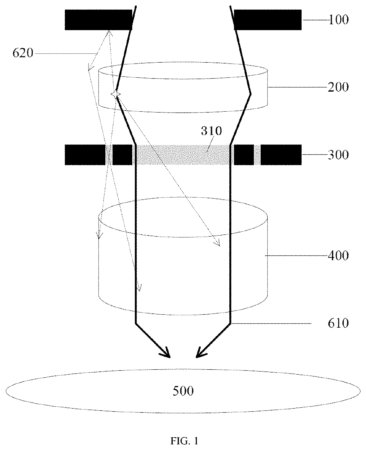
[0064]The present invention relates to the field of semiconductors, in particular to detection of the flare degree of a lens of an exposure machine table used in a semiconductor device photolithography process. The method for detecting the flare degree of the lens of the exposure machine table, provided in one aspect of the present invention, employs a photomask provided in another aspect of the present invention to expose photoresist on the upper surface of a test wafer, only stray light formed after exposure light passes through the lens reaches the photoresist on the upper surface of the test wafer, and according...


PUM


Abstract

Provided in the disclosure is a photomask for detecting flare degree of lens of exposure machine table. The photomask includes a central exposure area and a peripheral area, exposure light of the exposure machine table passing through the lens and then penetrating the central exposure area to expose photoresist on a wafer, wherein the entire central exposure area is provided with a shading layer to prevent the exposure light from penetrating; and the peripheral area is provided with a plurality of light-transmitting stripes, and stray light formed after the exposure light passes through the lens penetrates the plurality of light-transmitting stripes to expose the photoresist. Further provided in the disclosure is a method for detecting flare degree of lens of exposure machine table by using the photomask. According to the disclosure, a lens flare problem of an exposure machine table can be found and solved in time.

Description

CROSS-REFERENCES TO RELATED APPLICATIONS[0001]This application claims priority to Chinese patent application No. 202011125663.8, filed on Oct. 20, 2020, the disclosure of which is incorporated herein by reference in its entirety.TECHNICAL FIELD[0002]The present invention relates to the field of semiconductors, in particular to detection of the flare degree of a lens of an exposure machine table used in a semiconductor device photolithography process.BACKGROUND[0003]Photolithography means photo—litho—riting literally in Greek. Photolithography is a pattern transfer technology for transferring a pattern, on a mask, to a silicon wafer coated with photoresist and removing a specific part of a thin film on the surface of the silicon wafer by means of a series of production steps. Photolithography technology is a semiconductor key process technology developed on the basis of photographing technology and planographic printing technology.[0004]Light emitted by a light source irradiates the ...

Claims


Application Information

Patent Timeline
IPC IPC(8): G03F1/44G03F7/20
CPCG03F1/44G03F7/70591G03F7/70616G03F7/7085G03F1/84G03F7/70941
Inventor SONG, HAISHENGWANG, XIAOLONGZHOU, SHIJUN
Owner SHANGHAI HUALI MICROELECTRONICS CORP
Why Eureka
Try Eureka