A weight balancing gantry

a gantry and weight technology, applied in the direction of auxillary welding devices, soldering apparatus, hoisting equipment, etc., can solve the problems of reducing the strength affecting the stability so as to improve the resilience and weight bearing structural integrity reduce the width of the tower, and simplify the construction of the radial arm

Pending Publication Date: 2022-04-28
CUSCHIERI CLEM
View PDF0 Cites 1 Cited by
  • Summary
  • Abstract
  • Description
  • Claims
  • Application Information

AI Technical Summary

Benefits of technology

[0013]The length of the cable is determined such that, in the manner shown in FIG. 1, when the positioning mechanism is retracted, the length of cable between the bogey pulley and the industrial tool is lengthened so as to position the industrial tool at a lower proximal stowed position. The industrial cart may comprise a toolholder such that, when the industrial tool is at the lower proximal stowed position, the industrial tool can be easily be placed in the holder.
[0014]However, when the positioning mechanism is extended, the length of cable between the bogey pulley and the industrial tool shortens to move the industrial tool to a distal raised deployed position.
[0015]In the manner shown in FIG. 2, the radial arm can be raised by the angle strut to hoist the industrial tool over a high obstacle, such as a vehicle roof. When the radial arm is inclined at an angle in this way, the at least one cylinder of the positioning mechanism holds the bogey in place along the radial arm and prevents the bogey from running down the radial arm.
[0017]Furthermore, the fixed length radial arm having the bogey travelling therealong, simplifies the construction of the radial arm and increases the resilience and weight bearing structural integrity thereof.
[0018]The weight balancing mechanism may comprise collinear cylinders to reduce the width of the tower.

Problems solved by technology

The weight of these tools can range from 10-25 kgs depending on arm size used, making them heavy and awkward to use without the assistance of a weight balancing gantry.
However, when welding within the beaver panel (section under the boot lid and boot floor) of a vehicle for example, the cable may be obstructed by the boot lid.
Furthermore, the height of the roof of the vehicle may be too high for the radial arm.

Method used


Image

  • A weight balancing gantry
  • A weight balancing gantry

Examples


Embodiment Construction

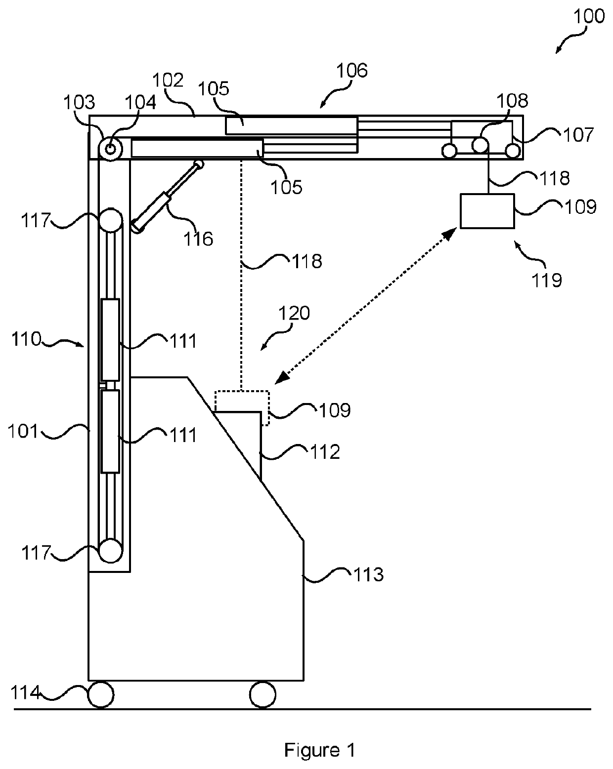
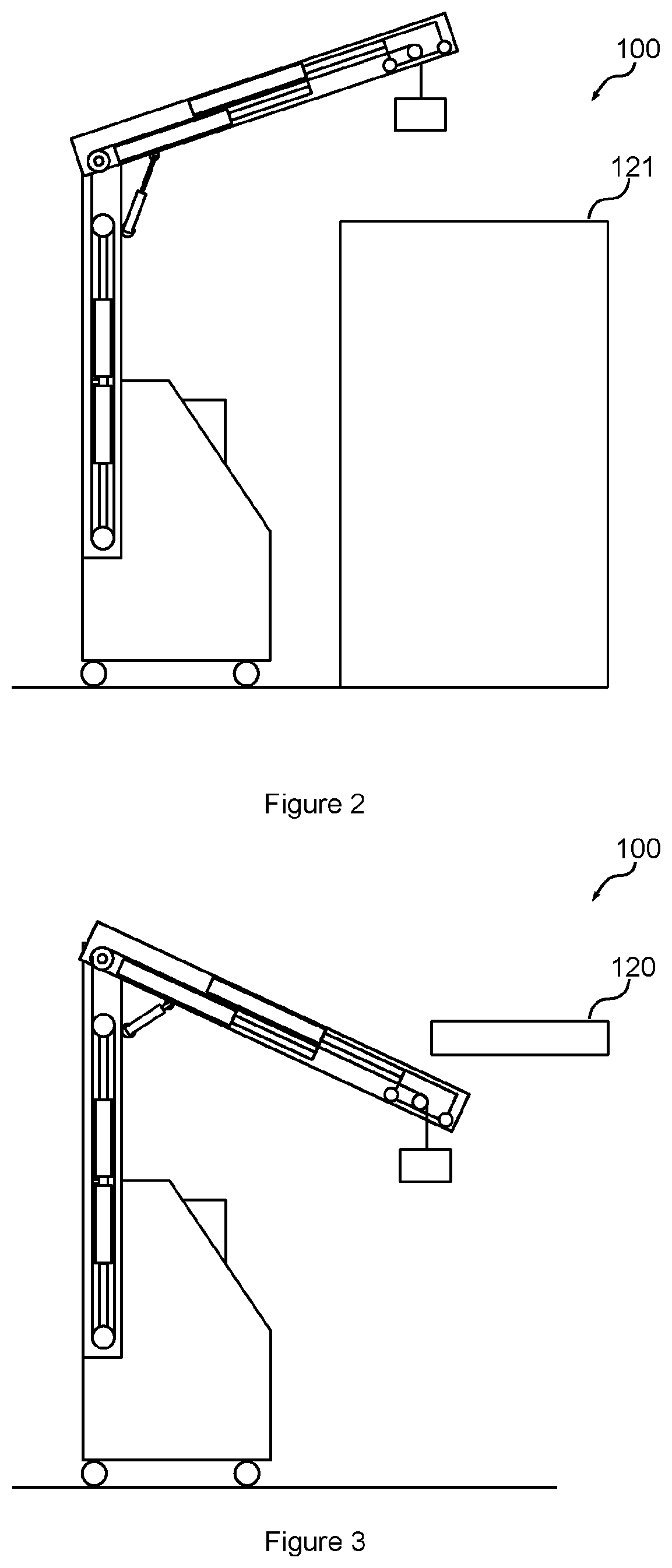
[0025]A weight balancing gantry 100 comprises a tower 101 having a radial arm 102 pivotally coupled from a pivot point 104 at an upper end of the tower 101 for supporting an industrial tool 109 such as a spot-welding gun.

[0026]The gantry 101 may be supported from an industrial cart 113 having castor wheels 114, such as a mobile spot welder.

[0027]An angle strut 116 acts between the tower 101 and the radial arm 102 across the pivot point 104.

[0028]In embodiments, the radial arm 102 may further swing side to side.

[0029]The gantry 100 comprises a weight balancing mechanism 110 which may comprise counteracting weight balancing pulleys 117. Each pulley 117 may be pneumatically biased from respective pneumatic cylinders 111, preferably in-line in the manner shown in FIG. 1 to reduce the overall width of the tower 101. In the embodiment shown, the weight balancing mechanism 110 is concealed within the tower 101.

[0030]In an embodiment, the balancing mechanism 110 may comprise a cheaper sprin...


PUM

PropertyMeasurementUnit
lengthaaaaaaaaaa
gravityaaaaaaaaaa
pressureaaaaaaaaaa

Abstract

A weight balancing gantry has a tower having a fixed length radial arm pivotally coupled from a pivot point at an upper end of the tower. An angle strut acts between the tower and the radial arm across the pivot point. A pivot point pulley is located at the upper end of the tower and a weight balancing mechanism located at the tower. A bogey runs along the radial arm and has a bogey pulley. A positioning mechanism at the radial arm has at least one controlled cylinder for positioning and holding the bogey along to the radial arm. A cable runs from the weight balancing mechanism, up across the pivot point pulley and over the bogey pulley to attach to an industrial tool.

Description

FIELD OF THE INVENTION[0001]This invention relates generally to a type of weight balancing gantry for balancing industrial tools, such as spot-welding guns.BACKGROUND OF THE INVENTION[0002]Weight balancing gantries are used in industry to vertically balance the weight of industrial tools, such as spot-welding guns in the car repair industry. The weight of these tools can range from 10-25 kgs depending on arm size used, making them heavy and awkward to use without the assistance of a weight balancing gantry.[0003]U.S. Pat. No. 2,176,979 A (Platz) 24 Oct. 1939 discloses a typical weight balancing gantry arrangement comprising a horizontal radial arm supported from a tower. A bogey runs along the horizontal radial arm and has pneumatic counterbalancing mechanism thereon from which a spot-welding gun is vertically balanced from a cable.[0004]U.S. Pat. No. 6,087,611 A (De Bruyn et al.) discloses a system for vertically balancing welding tongs which comprises a spring balance attached fro...

Claims


Application Information

Patent Timeline
Patent Type & Authority Applications(United States)
IPC IPC(8): B23Q1/00B23K11/11B23K11/31B23K37/02B23Q11/00B66C23/48B66C23/72
CPCB23Q1/0054B23K11/11B23K11/318B23K37/0235B66C23/72B23K37/0294B23Q11/001B66C23/48B23K37/0282B25H1/0028B23Q1/25B23K37/02B66D3/04
Inventor CUSCHIERI, CLEM
Owner CUSCHIERI CLEM
Why Eureka
Try Eureka