
Joined body and method of manufacturing joined body

a technology of joining body and metal member, which is applied in the direction of manufacturing tools, machines/engines, and so on, can solve the problems of limit in the increase of the oxidation resistance in the junction between the ceramic body and the metal member, and achieve the effects of reducing mechanical strength, reducing energizing performance, and easy oxidation

Pending Publication Date: 2022-05-05
NGK INSULATORS LTD
View PDF5 Cites 0 Cited by
  • Summary
  • Abstract
  • Description
  • Claims
  • Application Information

AI Technical Summary

Benefits of technology

This patent text discusses the problem of reducing the mechanical and electrical joint reliability of an electrode in a high temperature oxidation atmosphere commonly found in automobiles. The text describes how spraying layers to join the electrode to a substrate can lead to porous layers that easily oxidize and reduce reliability. The invention aims to solve this problem by providing a joined body that has high oxidation resistance in the junction between the electrode and the substrate. This can improve the reliability and performance of the electrode in high temperature environments.

Problems solved by technology

Further, also in the joining method disclosed in Document 2, since the junction layer becomes porous due to an influence of crystalline cordierite, or the like, there is a limitation in the increase of the oxidation resistance in the junction between the ceramic body and the metal member.

Method used


Image

  • Joined body and method of manufacturing joined body
  • Joined body and method of manufacturing joined body
  • Joined body and method of manufacturing joined body

Examples


Embodiment Construction

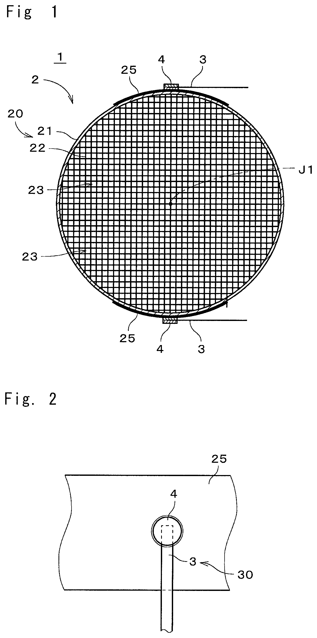
[0034]FIG. 1 is a cross section showing a joined body 1 in accordance with one preferred embodiment of the present invention. The joined body 1 is a columnar member which is long in one direction, and FIG. 1 shows a cross section perpendicular to a longitudinal direction of the joined body 1. The joined body 1 is used as an electrically heated catalyst (EHC) for performing a purification treatment of exhaust gas discharged from an engine of an automobile or the like or a heater for heating an object to be heated. Hereinafter, description will be made, assuming that the joined body 1 is the electrically heated catalyst.

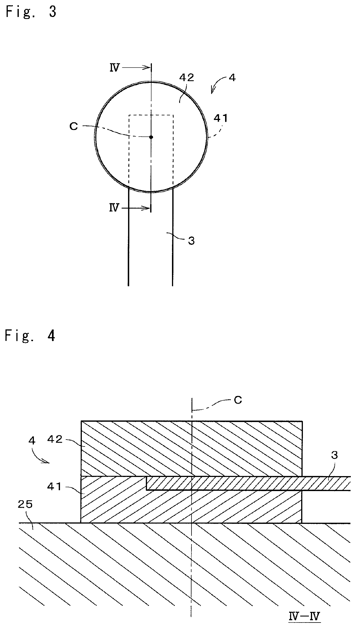
[0035]The joined body 1 includes a structure 2, an electrode part 3, and a junction part 4. The structure 2, the electrode part 3, and the junction part 4 are each conductive. The structure 2 is a carrier supporting a catalyst in the electrically heated catalyst. The electrode part 3 is fixed on a surface of the substantially columnar structure 2 by using the junction ...


PUM

PropertyMeasurementUnit
porositiesaaaaaaaaaa
thicknessaaaaaaaaaa
thicknessaaaaaaaaaa

Abstract

A joined body includes a junction target, an underlying layer, an electrode part, and a fixed layer. The conductive underlying layer is fixed on a surface of the junction target. The electrode part is fixed on the underlying layer. The conductive fixed layer is fixed on the underlying layer with the electrode part interposed therebetween. Respective porosities of the underlying layer and the fixed layer are each not higher than 10%.

Description

CROSS REFERENCE TO RELATED APPLICATION[0001]The present application claims the benefit of priority to Japanese Patent Application No. 2020-181757 filed on Oct. 29, 2020, the content of which is incorporated herein by reference in its entirety.TECHNICAL FIELD[0002]The present invention relates to a joined body and a method of manufacturing the joined body.BACKGROUND ART[0003]Conventionally, in order to perform a purification treatment of toxic substances such as HC, CO, NOx, or the like contained in exhaust gas discharged from an engine of an automobile or the like, a catalytic converter having a columnar honeycomb structure or the like which supports a catalyst has been used. In such a catalytic converter, the temperature of the catalyst needs to rise to an activation temperature in an exhaust gas purification treatment, but since the temperature of the catalytic converter is low immediately after startup of the engine, or so on, there is a possibility that the exhaust gas purificat...

Claims


Application Information

Patent Timeline
Patent Type & Authority Applications(United States)
IPC IPC(8): B23K35/02B23K35/36
CPCB23K35/0261B23K2101/06B23K35/361B23K35/3602F01N3/2803F01N3/2828F01N3/2026C04B37/02
Inventor SUZUKI, SHINJIKIMATA, TAKAFUMITOMITA, TAKAHIRO
Owner NGK INSULATORS LTD
Features
  • Generate Ideas
  • Intellectual Property
  • Life Sciences
  • Materials
  • Tech Scout
  • Unparalleled Data Quality
  • Higher Quality Content
  • 60% Fewer Hallucinations
Learn More