Accurate digital security system, method, and program
- Summary
- Abstract
- Description
- Claims
- Application Information
AI Technical Summary
Benefits of technology
Problems solved by technology
Method used
Image

Examples
embodiment
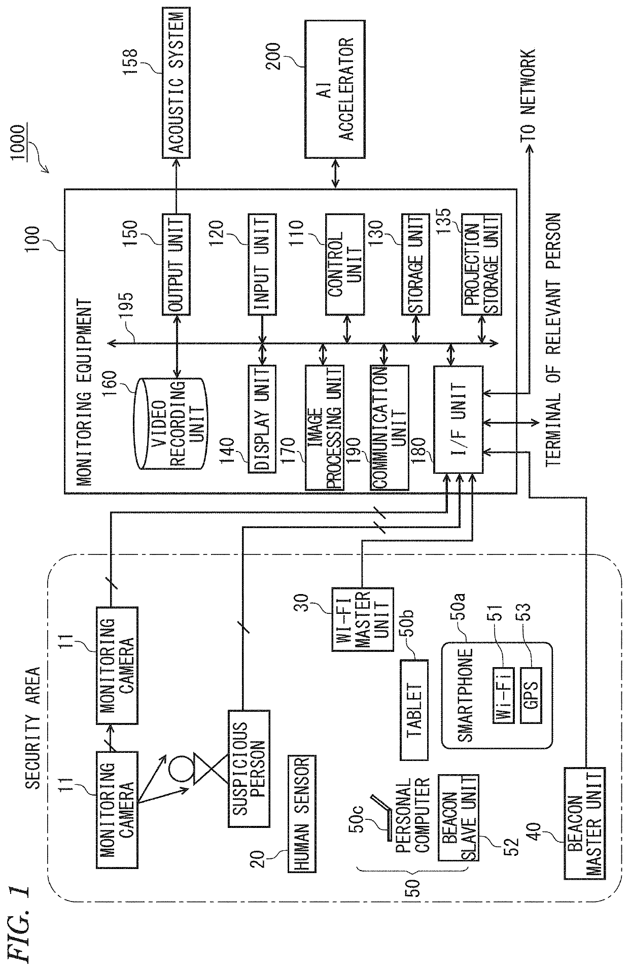
[0046]FIG. 1 is a block diagram showing a configuration of an accurate digital security system according to an embodiment of the present invention.
[0047]The present accurate digital security system is favorable for application in residences, offices of enterprises, factories, research laboratories, information processing rooms, monetary accounting rooms, and other places of business, etc., requiring high-level control.
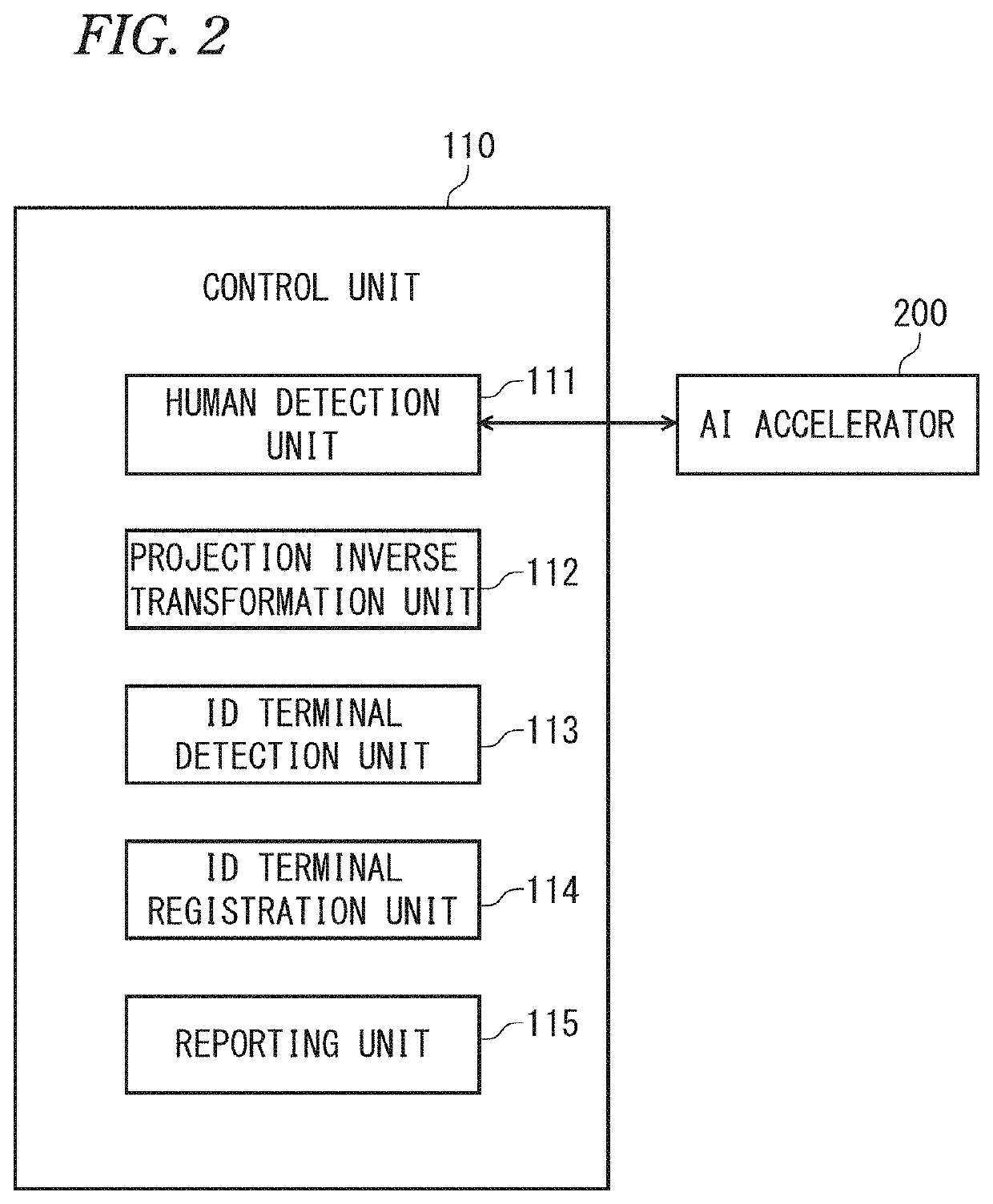
[0048]As shown in FIG. 1, the accurate digital security system 1000 comprises one monitoring cameras 11 (photographing means) installed in each security area, a human sensor 20, a Wi-Fi (wireless fidelity) terminal (hereinafter referred to as “Wi-Fi master unit”) 30 that is installed in the security area, a beacon master unit 40, mobile terminal devices 50 (ID (identification) terminals) that are carried by relevant persons (family members), a monitoring equipment 100 that controls the whole system, and an AI (artificial intelligence) accelerator 200 (human detection m...
application examples
[0239]Application examples of intrusion detection by the accurate digital security system shall now be described.
application example 1
[0240]FIG. 19 is a diagram for describing Application Example 1 of intrusion detection by the accurate digital security system 1000.
[0241]As shown in FIG. 19, the security yellow belt is set at an inside a site boundary and a security red belt is set across a security zone, surrounding a wall of a house with an entrance door and a window. Although FIG. 19 is a plan view, to indicate detection of an intruder by an elevation, (1) a horizontal position (X axis, Y axis) and (2) a vertical position (Z axis) vertical to the horizontal position are expressed by broken lines in regard to the intruder. That is, for the intruder, the above-described “position in three-dimensional space by the projection inverse transformation unit 112” is detected. Intruder detection in the elevation is executed similarly for suspicious persons (a squatting suspicious person and a lying-down suspicious person) in the security zone at a west side space and a south side space in FIG. 19.
[0242]FIG. 20 is a flowc...
PUM
 Abstract
Description
Claims
Application Information
 - Generate Ideas
- Intellectual Property
- Life Sciences
- Materials
- Tech Scout
- Unparalleled Data Quality
- Higher Quality Content
- 60% Fewer Hallucinations
Browse by: Latest US Patents, China's latest patents, Technical Efficacy Thesaurus, Application Domain, Technology Topic, Popular Technical Reports.
© 2025 PatSnap. All rights reserved.Legal|Privacy policy|Modern Slavery Act Transparency Statement|Sitemap|About US| Contact US: help@patsnap.com