Method and device used for relay wireless communication

a wireless communication and relay technology, applied in the field of wireless communication systems, can solve the problems of packet loss or higher-layer retransmission, reducing traffic quality, etc., and achieve the effect of shortening transmission delay and reducing packet loss

Pending Publication Date: 2022-05-05
SHANGHAI LANGBO COMM TECH CO LTD
View PDF0 Cites 1 Cited by
  • Summary
  • Abstract
  • Description
  • Claims
  • Application Information

AI Technical Summary

Benefits of technology

[0018]In one embodiment, a beneficial effect of the present disclosure includes: a status report of packets not successfully transmitted is fed back by an RN when a failure occurs in a radio link between the RN and a remote node, which can significantly reduce packet loss and shorten transmission delay at the same time.

Problems solved by technology

In one embodiment, a problem to be solved in the present disclosure is: when a failure occurs in a radio link between an RN and a remote node, packets not successfully transmitted buffered at the RN cannot continue to be transmitted to the remote node through the RN, which leads to packet loss or higher-layer retransmission, thus reducing traffic quality.

Method used


Image

  • Method and device used for relay wireless communication
  • Method and device used for relay wireless communication
  • Method and device used for relay wireless communication

Examples


embodiment 1

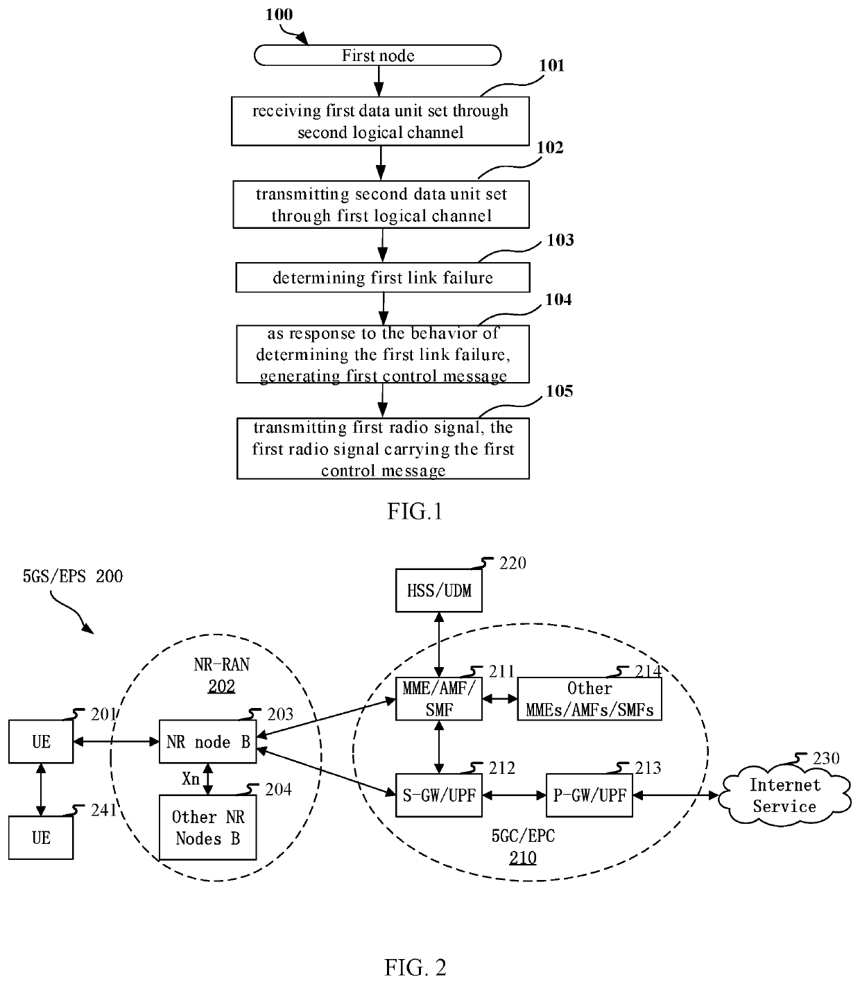
[0082]Embodiment 1 illustrates a flowchart of transmission of a first node according to one embodiment of the present disclosure, as shown in FIG. 1.

[0083]In Embodiment 1, a first node 100 receives a first data unit set through a second logical channel in step 101; transmits a second data unit set through a first logical channel in step 102; determines a first link failure in step 103; as a response to the behavior of determining the first link failure, generates a first control message in step 104; transmits a first radio signal in step 105, the first radio signal carrying the first control message; herein, the first data unit set comprises at least one data unit; the second data unit set comprises at least one data unit; the first control message is used to indicate that a third data unit set is not successfully transmitted; any data unit in the third data unit set belongs to the first data unit set; any bit in the second data unit set belongs to the first data unit set; and a dat...

embodiment 2

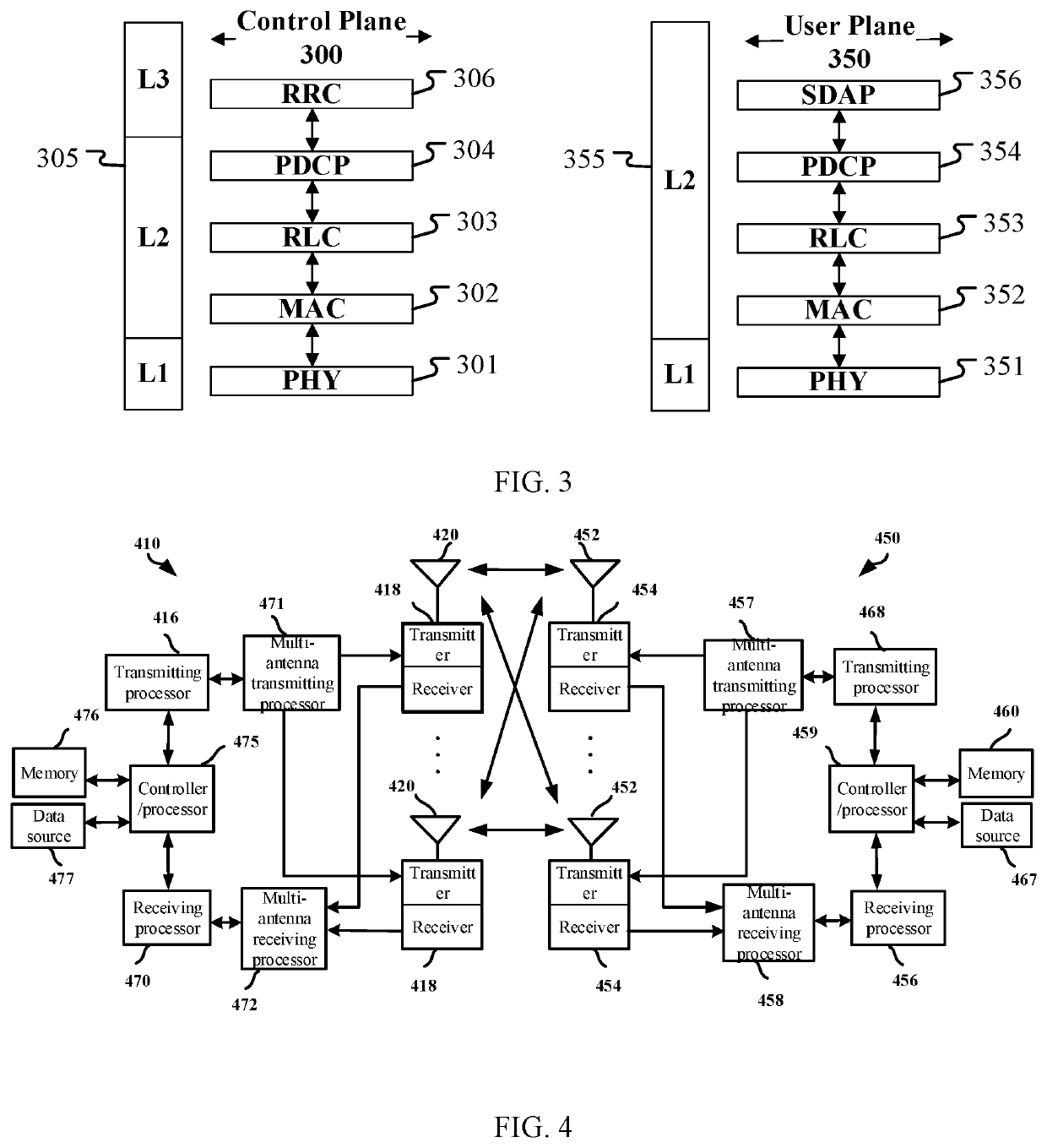
[0166]Embodiment 2 illustrates a schematic diagram of a network architecture according to one embodiment of the present disclosure, as shown in FIG. 2. FIG. 2 is a diagram illustrating a network architecture 200 of 5G NR, Long-Term Evolution (LTE), and Long-Term Evolution Advanced (LTE-A) systems. The NR 5G, LTE or LTE-A network architecture 200 may be called a 5G System (5GS) / Evolved Packet System (EPS) 200 or other appropriate terms. The 5GS / EPS 200 may comprise one or more UEs 201, an NG-RAN 202, a 5G-Core Network / Evolved Packet Core (5GC / EPC) 210, a Home Subscriber Server (HSS) / Unified Data Management (UDM) 220 and an Internet Service 230. The 5GS / EPS 200 may be interconnected with other access networks. For simple description, the entities / interfaces are not shown. As shown in FIG. 2, the 5GS / EPS 200 provides packet switching services. Those skilled in the art will readily understand that various concepts presented throughout the present disclosure can be extended to networks p...

embodiment 3

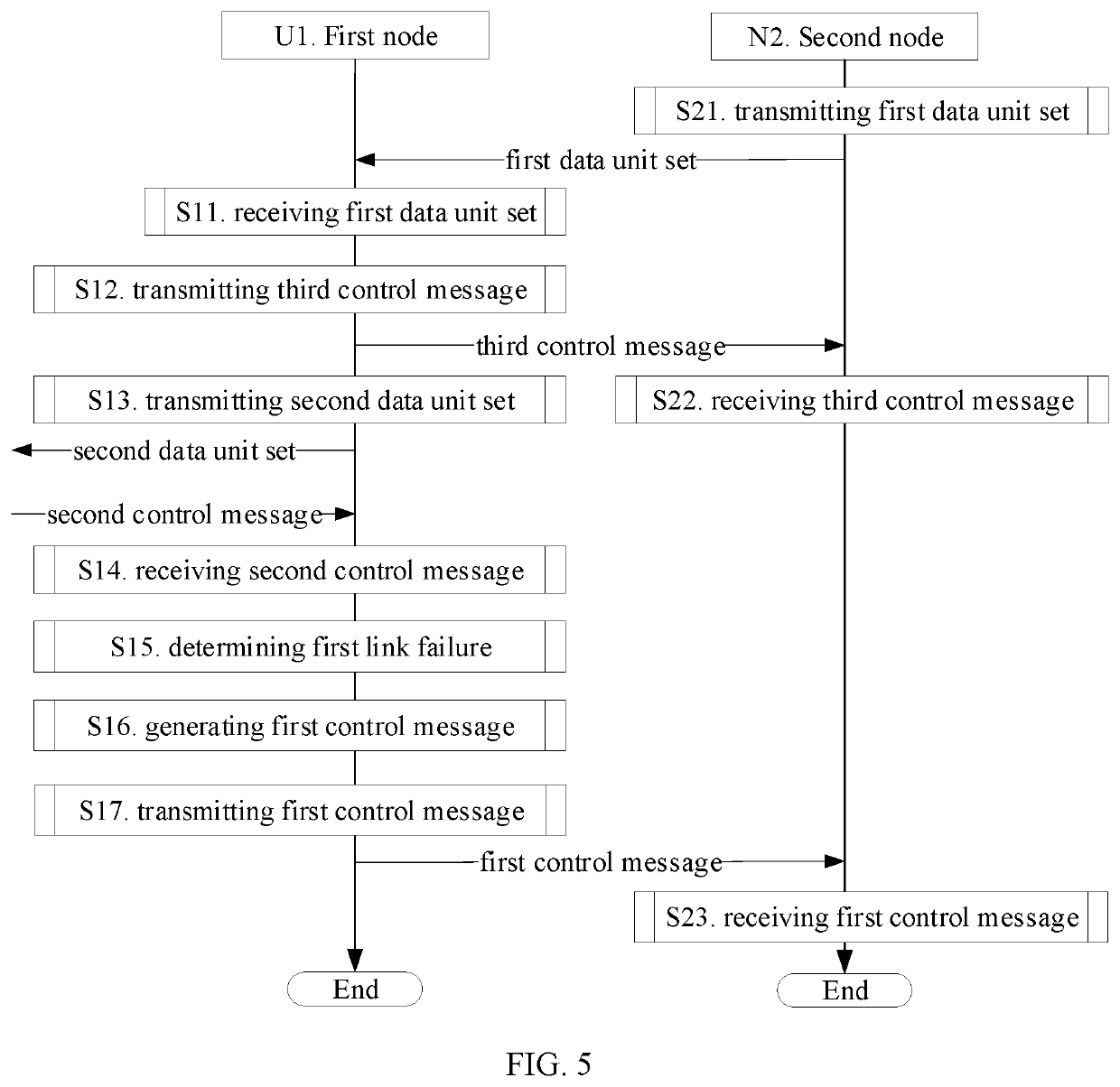
[0183]Embodiment 3 illustrates a schematic diagram of a radio protocol architecture of a user plane and a control plane according to one embodiment of the present disclosure, as shown in FIG. 3. FIG. 3 is a schematic diagram illustrating an embodiment of a radio protocol architecture of a user plane 350 and a control plane 300. In FIG. 3, the radio protocol architecture for the control plane 300 of a UE and a gNB is represented by three layers, which are a layer 1, a layer 2 and a layer 3, respectively. The layer 1 (L1) is the lowest layer and performs signal processing functions of various PHY layers. The L1 is called PHY 301 in the present disclosure. The layer 2 (L2) 305 is above the PHY 301, and is in charge of the link between the UE and the gNB via the PHY 301. L2 305 comprises a Medium Access Control (MAC) sublayer 302, a Radio Link Control (RLC) sublayer 303 and a Packet Data Convergence Protocol (PDCP) sublayer 304. All the three sublayers terminate at the gNBs of the netwo...


PUM


Abstract

A method and device for relay wireless communications. A first node receives a first data unit set through a second logical channel; transmits a second data unit set through a first logical channel; determines a first link failure; as a response to the behavior of determining the first link failure, generates a first control message; and transmits the first control message; herein, the first control message is used to indicate that a third data unit set is not successfully transmitted; any data unit in the third data unit set belongs to the first data unit set; any bit in the second data unit set belongs to the first data unit set. In the relay transmission of the present disclosure, when a link fails, a relay node transmits a status report of packets not successfully transmitted to a source node, so as to reduce packet loss and shorten transmission delay.

Description

CROSS REFERENCE TO RELATED APPLICATIONS[0001]This application claims the priority benefit of Chinese Patent Application No. 202011222991.X, filed on Nov. 5, 2020, the full disclosure of which is incorporated herein by reference.BACKGROUNDTechnical Field[0002]The present disclosure relates to methods and devices in wireless communication systems, and in particular to a method and device for reporting transmission status due to a radio link failure in relay wireless communications.Related Art[0003]As a multi-hop transmission technology, relay can increase throughput and expand coverage. Relay communication is a common method in cellular network communications. Data from a source node is forwarded by a relay node (RN) to a remote node. The source node and the remote node are usually a base station and a User Equipment (UE), or both UEs; the relay node may be a network device or a UE. Taking Sidelink (SL) transmission in Long Term Evolution (LTE) system as an example, a transmission fro...

Claims


Application Information

Patent Timeline
Patent Type & Authority Applications(United States)
IPC IPC(8): H04W28/02
CPCH04W28/0205H04W16/26H04W28/0278H04W28/14
Inventor ZHANG, XIAOBO
Owner SHANGHAI LANGBO COMM TECH CO LTD
Why Eureka
Try Eureka